Abstract: Accurately simulating the preload of bolts in finite element analysis of bolted joints is a complex and difficult task. The pre-tightening element method, cooling method and osmotic contact method for simulating bolt pre-tightening force in ANSYS using finite element technology are discussed. By comparison, it is found that the pre-tightening element method can better simulate the actual pre-tightening force, which provides a reliable theory and application basis for applying the pre-tightening load in the finite element analysis.
Tensioned bolt connections are the most widely used coupling method in mechanical construction. Most threaded joints must be tightened during assembly so that the joint is pre-stressed before it is subjected to the working load. This pre-energizing force is called pre-tightening force. The purpose of the pre-tightening is to enhance the reliability and tightness of the joint to prevent gaps or relative slippage between the coupled members after being loaded. For the finite element analysis of the mechanical structure with bolted joints, how to apply it to the model, it is difficult to simulate the bolt stress condition to achieve accurate loading in the finite element analysis and get the correct analysis result. In this paper, the preload force unit method, temperature method and osmotic contact method are used to simulate the bolt preload force loading in ANSYS. The three methods are compared.
1. Calculation of bolt preload
The value of the preload force Qp should be determined according to the nature of the load, the joint stiffness and the like. The preload applied during use is given by the torque T applied by the tightening nut, which can be measured using a force wrench when tightening the nut. The tightening torque T is equal to the frictional resistance torque T1 between the screw pair and the frictional resistance torque T2 between the annular end face of the nut and the bearing surface of the coupled member (or washer), namely:
T = T1 + T2 (1)
The frictional torque between the spiral pairs is:
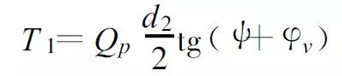 (2)
(2) The frictional torque between the nut and the bearing surface is:
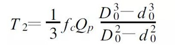 (3)
(3) Substituting (2) and (3) into (1)
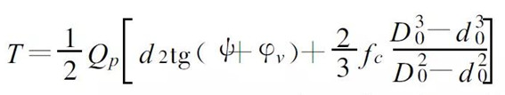 (4)
(4) For steel bolts of M10~M64 coarse internal thread, the thread angle ψ=1°42′~ 3°2′; the thread diameter d 2 ≈0.99d; the equivalent friction angle of the screw pair φv =arctg1 .155 f (f is the coefficient of friction, f ≈0.1 to 0.2 when there is no lubrication); bolt hole diameter d 0 ≈1 .1 d; outer diameter of the nut annular bearing surface D0 ≈1 .5d; between the nut and the bearing surface The friction coefficient fc = 0.15. By substituting the above parameters into (4), T ≈0 .2Qpd (5) can be obtained.
Therefore the bolt preload is:
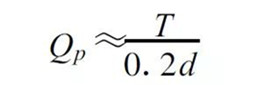 (6)
(6) 2. Simulation of bolt preload
Under the pre-tightening force, the bolt is in the tension state, and the connected member is pressed. If the balance load applied to both ends of the rod unit is used, the actual force can not be simulated in any direction.
In the general finite element analysis software ANSYS, the following methods can be used to simulate the loading of the bolt preload.
2.1 Using the preload force unit method to simulate the bolt preload
ANSYS provides pre-tensioning units PRETS179 and PTSMESH pre-stretching subnet operations to simulate bolt preload. The coupling is described by a 3-D solid structure, and the pre-tensioning unit PRETS179 simulates a pre-stretch section at the screw model joint. The easiest way to apply a preload unit on a coupling is to use the PSMESH command to define the preload section and create a preload unit. It automatically cuts the meshed joint into two parts and inserts the preload force unit to directly load the preload force Qp onto the unit. The preload unit is shown in Figure 1.
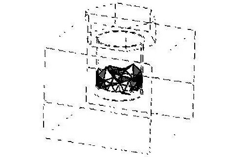
Figure 1 bolt preloading unit diagram
2.2 Using the cooling method to simulate the bolt preload
A decrease in temperature will cause the object to shrink and deform, and the deformation of the structure will be constrained, resulting in internal tension. The cooling method can be used to simulate the bolt preload condition. The basic idea is to convert the initial load into the bolts of the corresponding temperature load. Assume that the pre-tightening force is not generated on the bolts originally installed on the bolts. When the bolts have a negative temperature load (assuming the initial temperature is 0) and the other components are at the same temperature, the bolts must contract, and the bolts must be subjected to a pulling force to prevent them from being free. Shrinkage, while the coupled parts are under pressure. The preload can be simulated by scaling the temperature load to the initial load applied to the bolt. Assume that the bolt material has a coefficient of expansion of a. Initial load Qp of the bolt rod, and calculate the initial deformation of the bolt under the initial load
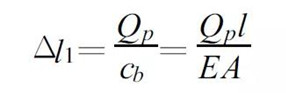 (7)
(7) Deformation of the coupled part
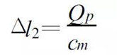 (8)
(8) Where cb is the bolt stiffness and cm is the stiffness of the coupled part. The pre-tightening torque is applied to the bolt connection in the unstressed state, and the screw is continuously extended by the relative movement (screwing) between the nut and the bolt rod, and the chassis around the screw hole is continuously compressed. The tensile force received in the bolt rod is in equilibrium with the compression force received in the chassis through the nut and increases as the pre-tightening torque increases. The total deformation of the bolt rod and the connected parts is:
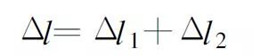 (9)
(9) make
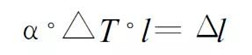 (10)
(10) ΔT is the temperature load acting on the bolt relative to the initial temperature.
Namely: ΔT = T 0 - T bolt (11)
then:
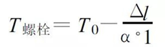 (12)
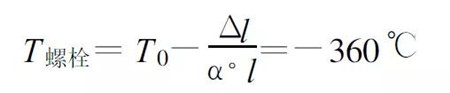
(12) The initial temperature selection does not affect the calculation, let T0 =0, then:
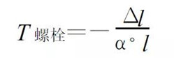 (13)
(13) The initial load is converted into a temperature load and loaded onto the bolt rod.
2.3 Simulating bolt preload by osmotic contact method
The pre-tightening force of the bolt can be simulated by the contact pair provided by ANSYS. as shown in picture 2. Firstly, when the bolt rod is built, the total deformation of the screw and the coupled member after the pre-tightening torque is applied is subtracted, and then the contact pair is established. The screw is subjected to the pulling force, and the tension is applied to the coupling member to simulate the pre-tightening force of the bolt.
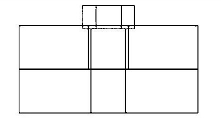
Figure 2 Schematic diagram of bolt rod penetration contact
Firstly, according to the formulas (7), (8), (9), the deformation amount of the screw under the preload force and the deformation amount of the coupled member are calculated.
The sum Δl is subtracted directly from the screw during modeling, so the length of the screw is:
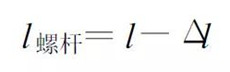 (14)
(14) 3, examples
Take the M24 bolt as an example, the screw length l = 30mm, diameter d = 24mm, nut diameter 39.55mm, height 13mm, pre-tightening torque T = 1020Nm, elastic modulus E = 2.1 × 10⁵MPa, Poisson's ratio μ = 0 .3 , thermal expansion coefficient a =0 .000012 / ° C. The pre-tightening force Qp ≈ 212500N bolt rod deformation amount Δl 1 = 6.7 × 10⁻² mm by the coupling deformation amount Δl 2 = 6. 26 × 10-2mm total deformation Δl = 1.296 × 10⁻¹mm. The initial ambient temperature T0 =0, then
 (15)
(15) The screw tension caused by the pre-tightening force Qp is:
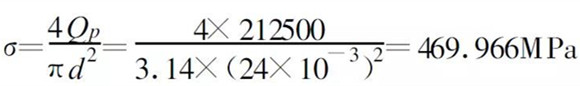 (16)
(16) The three methods described in 2 are used to simulate the preload force of the bolt. The solid92 unit is selected in ANSYS.
3.1 Preload unit
The finite element model is shown in Figure 3. The number of divided units is 8859 and the number of nodes is 13766. In the middle of the screw, the axial average stress is about 470 MPa, which is basically consistent with the calculated tensile stress value of 469.966 MPa, which is consistent with the actual situation. Because the preloading force is used, the preloading load is directly loaded on the screw, and is not affected by the model. The effect of the number of divisions of the unit simulates the bolt preload. Its axial stress cloud diagram is shown in Figure 4.
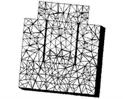
Figure 3 bolt connection finite element model
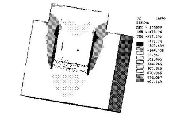
Figure 4 Prestressing element axial stress cloud diagram
3.2 cooling method
The finite element model is consistent with Figure 3. The calculated results of the axial stress cloud of the screw are shown in Figure 5. In the middle of the screw, the axial average stress is about 500 MPa, which is larger than the calculated value, and the stress distribution is not uniform, especially the tensile stress near the axial portion of the screw is too large, and the tensile stress away from the axial portion is small, which is mainly due to the cooling method. When the temperature is lowered, the screw not only generates compressive stress in the axial direction but also generates radial compressive stress in the radial direction.
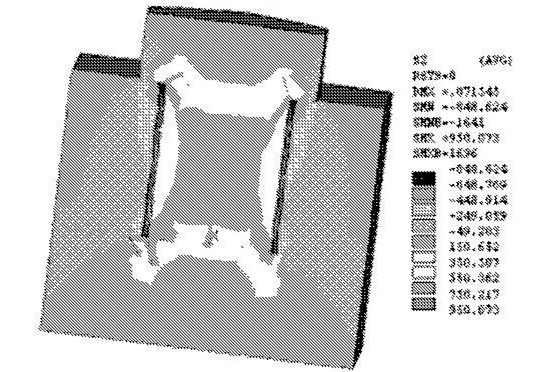
Figure 5 Cooling method screw axial stress cloud diagram
3.3 Initial osmosis contact method
The number of units divided by the finite element model is 8232, and the number of nodes is 13499. The results of the calculation of the screw axial stress cloud are shown in Fig. 6. Similarly, in the middle of the screw, the average axial stress of the screw is about 450 MPa, which is less than the theoretical value.
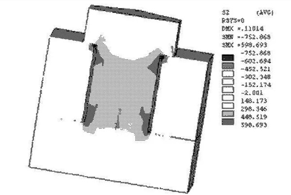
Figure 6 osmotic contact axial stress cloud
4 Conclusion
The results calculated by the cooling method and the osmotic contact method are quite different from the theoretical values, and the preload force unit method is used to simulate the bolt preload force. The reason is that in the preloading force method, the preloading load is directly loaded on the screw, which is less affected by factors such as the number of units divided by the model, so that the bolt preloading force can be well simulated; and the cooling method and the osmotic contact method are well The number of elements divided by the model has a great influence, and when the temperature is lowered, the screw not only generates compressive stress in the axial direction, but also generates compressive stress in the radial direction, which tends to increase the overall stress of the bolt.
Author: Lihui Xun, Hu Yingchun, Zhang Jianzhong
Source: School of Mechanical Engineering, Guangxi University
Department of Computer Engineering, Guangxi University of Technology
Department of Mechanical Engineering, Shandong University of Science and Technology
Fluorescent Coating,Organic Resin Kit,Fluorescent Coating Films,Ethylene Glycol Diacetate
XINGZHILIAN BIOLOGICALR&D CO.,LTD , https://www.xzlsdslds.com