1 Introduction
In the field of mechanical design, due to the intensified market competition, users have higher and higher requirements for product production efficiency, so advanced design techniques must be adopted. In the late 1970s, due to the mutual penetration and combination of computer technology and mechanical design technology, computer-aided design, referred to as CAD technology, was produced. The representative softwares were Pro/E, Solidworks, SolidEdge, UG and CATIA. With the development of science and technology, some new application technologies, such as computer-aided engineering technology, namely CAE technology, have appeared. The representative softwares include ANSYS, ALGOR, ABAQUS, MARK and NASTRAN.
CAD/CAE technology has the advantages of comprehensive, high-tech content and quick effect, and is one of the fastest growing application technologies. According to the statistics. By the early 1990s, the application of CAD/CAE technology had entered nearly 100 industrial fields such as machinery, electronics and architecture. The application of CAD/CAE technology to the machinery industry can greatly improve product quality, shorten product design and development cycles, and reduce product costs.
At present, CAD/CAE technology is still in its infancy in the design of railway vehicle parts. For this reason, the export of New Zealand passenger car bogies by a passenger car factory is taken as an example. The CAD/CAE technology is discussed in detail in the wheelset design. Application process. The example 3D modeling application Solidworks software, the calculation and analysis application ANSYS software.
2 Mechanical design application of CAD/CAE technology
Solidworks software is the mainstream 3D design software based on Windows/NT platform. It can not only record the modeling process of the whole model reasonably and effectively, but also allow users to modify and convey the design concept and process framework of the model construction at will. Its characteristics are: the model size can be changed at any time, the associated conditions can be added and the geometric dimensions can be modified. The features can be mutually adjusted or restored to the previous state, and all design materials can be edited and modified; parts. Components and drawings are interactive and can be updated and always the most accurate design. Its 3D modeling is powerful, easy to operate, and has strong data exchange capabilities with other design and analysis software.
The use of three-dimensional finite element method to solve a variety of engineering and technical problems is an indispensable important link in engineering design analysis activities, and also one of the important development directions in the field of computer-aided design. ANSYS is a large-scale general CAE software that integrates structure, fluid, electric field, magnetic field and sound field analysis. It is a finite element analysis software which is famous for its high algorithm rate and wide application type. However, it has the disadvantages of cumbersome pre-processing and difficult modification. Especially when building a more complex 3D solid model, it takes a lot of time and effort, and its modeling function is difficult.
If the Solidworks software and ANSYS software are effectively combined, the advantages are complementary, and the powerful modeling function of SolidWorks is used for component modeling and assembly. Then the corresponding finite element analysis is carried out in ANSYS, so that the CAD/CAE software can be used. Advantages can greatly improve the efficiency of building a solid model, reduce modeling errors, and have positive significance for structural analysis and optimization design of wheelsets. This paper studies the wheelset design based on this application.
However, the output of 3D models from Solidworks software to ANSYS software is likely to cause the loss of primitives and the unsuitability of the model for meshing. This requires some repair work on the model in ANSYS. The example of this article also introduces the application operation in detail for this situation.
3 CAD application in wheelset design
3.1 Wheelset structure features
The wheels designed by a bus factory are integral milled wheels. The material is made of CL60 steel, and the axle material is LZ50 steel, which is a solid shaft. The diameter of the mating surface of the axle and the hub is 185mm, and the effective contact length of the axle is 145.6mm. The wheel rim is 155mm wide and 73mm thick, and the outer diameter of the hub is 258mm. The axle shaft fit interference ratio is (0.8-1.5) ‰. Considering that the wear wheel is inferior to the new wheel, the wear wheel is selected as the calculation object, and the diameter of the wear wheel is 723 mm.
Refer to the relevant technical parameters, as shown in Table 1.
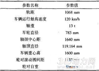
Table 1 main technical parameters of the wheel set
3.2 wheelset solid modeling
According to the wheelset structure characteristics and related dimensions described in Section 2.1, Solidworks software can be used to generate three-dimensional maps of wheels and axles respectively, and then wheel and shaft assembly according to the size requirements, and complete the three-dimensional solid modeling of the wheelset, as shown in Figure 1. .
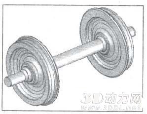
Figure 1 Wheelset model diagram created in Solidworks software
3.3 round to the output of the solid model
IGES is a generally accepted intermediate standard format that allows geometric models to be exchanged between different CAD and CAE systems. ANSYS' iGES input capability is the strongest in the industry, and because the filter program can import partial files, at least some parts of the model can be entered. After modeling in Solidworks, click the "File" command in the Tools menu, click "Save As" in the drop-down menu, and click the IGES (*.igs) file format in the type options of the subsequent dialog box, as shown in Figure 2. As shown, after the determination, the wheelset model is output.
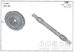
Figure 2 Wheelset model output
4 rounds of CAE analysis
4.1 Input wheelset model
Open the ANSYS software, click the drop-down menu File\import\IGES, the Import IGES File dialog box appears, click "OK" according to the default options, enter the next dialog box, specify the working path of the IGES file save, and open. The Solidworks model will be imported into ANSYS as IGES. Enter the wheelset model as shown in Figure 3.

Figure 3 Wheelset model input into ANSYS
After the Solidworks model is input into ANSYS in the form of IGES, it can be found that the curved surface is lost and the partial assembly relationship is lost. It can be seen from Fig. 3 that the wheel and the shaft have been separated; since the wheel surface has been lost, the wheel body is no longer present, but the wheel line and key points can be entered.
This requires partial modification of the model in ANSYS software. Here, you can also return to the wheelset model in Solidworks software, simplify the parts of the model that hardly affect the finite element calculation, or modify the type of the output model, such as *.step and *.sat, but enter the ANSYS software. There will be different degrees of body, surface and line loss. Select the IGES format input model and modify the model in ANSYS software.
4.2 Model modification
Although the modeling capabilities of AYSYS software are not very good, the general modeling operations are still very easy to implement. Since line features can be entered, missing face features or body features can be regenerated based on line features. In the input model, the wheel and the shaft are separated, and the wheel can be moved or rotated to finally generate a wheel pair model that is transferred according to the size requirement.
4.3 wheel pair discretization
In actual use, the wheel and the axle are assembled together into a wheel pair, so the wheel pair is taken as a research object. Based on the structural characteristics of the wheelset, it is discretized into a solid element Solid45 for finite element modeling. The axle fit is an interference fit. During the finite element modeling process, the wheelset simulates the interference fit with the conta174 and targe170 contact elements. The number of cells in the discrete model is 99,431, and the number of nodes is 107,743. The discrete wheel pair finite element model is shown in Figure 4.
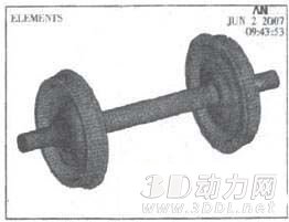
Figure 4 wheelset finite element model
4.4 Wheelset loading conditions and constraint processing
Wheelsets are subjected to a variety of complex loads during operation. The radial and lateral forces of the wheel on the wheel, the different interference of the wheelset press, and the centrifugal force caused by the rotation at high speed have a great influence on the stress distribution of the wheel.
Since the axle axle fit is an interference fit, different press fits have a large influence on the stress of the wheel, and at the same time have a great influence on the axle press fit and tightness, so the calculation considers the minimum and maximum interference respectively. The strength of the lower wheel under various working conditions.
According to the load of the wheel pair in the actual operation process, the following six operational load calculation conditions are considered for the finite element calculation of the wheelset:
The working condition 3 and the working condition 5 simulate the load on the wheel when the vehicle passes the curve, and the working condition 4 and the working condition 6 simulate the load on the wheel when the vehicle is traveling straight. The load reference standard "Vehicle Axle Design and Strength Calculation Method" (TB/T 2705-1996) is used in each working condition.
According to the actual operation and the force state of the wheel pair, the working condition 1 and the working condition 2 impose a fixed displacement constraint on the section of the journal, and the working condition 3 to the working condition 6 impose a fixed displacement constraint on the node where the wheel pair contacts the track.
4.5 Static strength calculation results
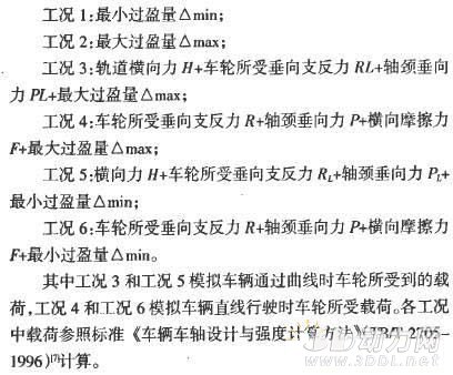
Through the design and finite element analysis of the bogie wheelset, the stress and strain distribution diagrams under six working conditions are obtained. The maximum stress of the wheel under the six working conditions is on the outside of the wheel. The maximum stress of the wheel and axle occurs in working condition 3. The maximum stress occurring is 292.343 MPa; the maximum stress of the axle appears in the center of the wheel seat, and the maximum stress occurring is 138.634 MPa. For reasons of space, only the equivalent stress cloud diagram of the wheel and axle of the working condition 3 is listed here, as shown in Fig. 5 and Fig. 6.
Compared with the allowable stress of 405 MPa under the applied load of the wheel and the allowable stress of 269 MPa under the applied load of the axle, the design wheel is safe to use.
It can be concluded that the strength analysis of the wheel and axle by the finite element method shows that the structural static strength of the wheel axle considering different interference can meet the requirements, and the wheelset design scheme is feasible.
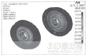
Figure 5 working condition three wheel equivalent stress cloud
Figure 6 three-axle equivalent stress cloud diagram
5 Conclusion
Taking the export of New Zealand passenger car bogies as an example, CAD (Solidworks) software and CAE (ANSYS) software are used for modeling and structural analysis, which provides a reliable design basis for subsequent wheel alignment optimization.
(1) The wheelset designed by the bus factory is reasonable and can meet various operating conditions and be safe to use.
(2) Using the effective integration technology of CAD software and CAF software, the data conversion of modeling is realized. Compared with the modeling method directly in CAE software, the combination of CAD modeling and CAE modeling calculation can be used. Accelerate the speed of solid modeling, and practice has proved that this method is feasible.
(3) It is just an example of combining existing design tools in the field of mechanical design. How to better apply advanced technology to engineering design and maximize the potential of existing technologies and tools. It has become a problem that designers have to think about in the process of practice, and has broad application prospects.
Rubber Sheets Bed,Rubber Sheet Warehouse,Rubber Sheet Flooring,Rubber Sheet Lowes
EPDM Rubber Flooring,Bumper PlateCo., Lt d , http://www.nbconveyorbelts.com