1. Product introduction
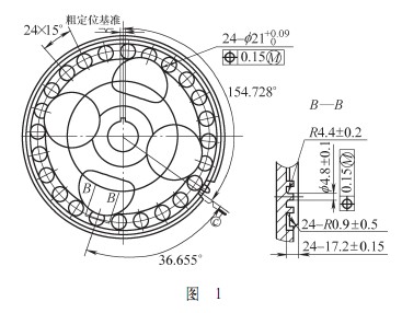
The part shown in Fig. 1 is a camshaft gear recently processed by our company. The gear is a disc-shaped part with a large outer diameter and a thin thickness, and has high precision requirements. It can be seen from Figure 1 that the part needs to: 1 process a single key, the machining accuracy of the key affects the exact positioning of the part and the engine camshaft, and the centerline of the key and the angle of the centerline of the tooth groove determine the timing mark. Processing accuracy. 2 Milling 24 φ21mm counterbore (one of which is cored), with the core hole as the ignition mark and the remaining holes as the timing mark. Their machining accuracy determines the timing of the engine's valve timing and ignition timing. If the traditional processing method is used, it is almost impossible to achieve the pattern requirement by using a drilling machine on the radial drilling machine. At present, our company uses the horizontal broaching machine model L6120C and the model VMC1060 vertical machining center to complete the above process.
2. Problems in the processing of products and their causes
In the trial production process, 80% of the holes in the processed holes are out of tolerance, both at 0.25 mm, and the bottom of the holes is uneven. The tools used in this part are high-speed steel, 23 φ21mm counterbored roughing cutters and fine milling cutters are all equipped with keyway milling cutters, and the testing equipment is a three-coordinate measuring instrument. When the process is completed, the process takes 19 minutes, and obviously, the processing time is long.
Serious analysis of the above problems, there may be five reasons: 1 cutting amount is selected. 2 processing procedures. 3 The workpiece coordinate system established by machining. 4 The roughing and fine milling cutter cutting edges are not smoothed. 5 According to the normal processing, the machining allowance of 0.2mm is left to the bottom surface, and the rigidity of the keyway milling cutter is insufficient, causing the tool vibration and affecting the position of the workpiece.
For the above reasons, combined with the experience of processing other workpieces, one-to-one analysis and summary:
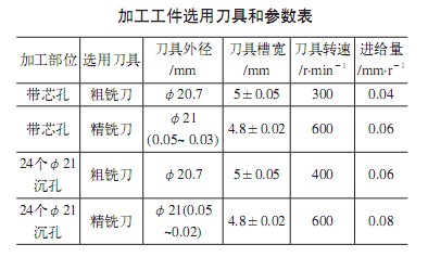
(1) When the cutting amount is selected, the material used for the workpiece is SCM420H (corresponding to domestic 20CrMo), and its tensile strength σ=900MPa. The selected tools and parameters are shown in the attached table.
(2) Part program: further modify the program, re-program the relative coordinates to absolute coordinates, and there is no difference after the workpiece is inspected after processing.
(3) Workpiece coordinate system: After repeated rectification, the positioning accuracy is within 0.01mm.
(4) The rough milling cutter and the finishing cutter have a concave surface on the bottom surface. After the cylindrical grinding machine is placed on the flat bottom surface, the tool grinding reopens the back angle, and the back angle is 6° to 8°.
(5) Considering the lack of rigidity of the keyway cutter, the centering accuracy is not high, causing the vibration of the tool and causing the position of the workpiece to be out of tolerance: for this problem, the fine milling cutter has just contacted the bottom plane of 0.02 to 0.03 mm. In this way, the positional requirements of the machined workpiece are guaranteed, generally within 0.06mm, and the surface roughness can fully meet the process requirements; after the product is finished, the fine milling cutter is changed to a hard alloy milling cutter, and the product has a core hole. The outer diameter of the finishing cutter is φ210 . 0 40 mm, the speed of the finishing cutter with core hole is 800r/min, the feed rate is 0.05mm/r; the speed of rough milling cutter of φ21mm hole is 1 000r/min, the feed rate It is 0.08 mm/r. The processing time is shortened by 12 minutes, and the processing quality is greatly improved.
3. Processing and adjustment of special inspection tools
It turns out that every time the machine is adjusted or the tool is changed again, the first piece must be checked on the three coordinates, and each shift must be checked at the three coordinates at a sampling rate of 1/20. As a result, the efficiency is low and cannot meet the demand for expansion.
Due to the dimensional error and shape error of the workpiece, the size, shape and position error will affect the actual contour of the part. According to the independent principle of tolerance requirements and related principles (inclusive principle and maximum physical principle), the special inspection tool shown in Figure 2 is designed and manufactured.
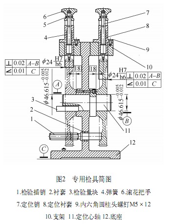
Inspection tool processing: The inspection tool processes 12 φ28mm holes on the coordinate boring machine to ensure that the angle between one hole and the bracket 10 is 36.655°, and the other holes are evenly distributed, and the position of each hole is not more than φ0.012mm. Then, the grinding bush 2 and the 12 holes of φ28H7 have an interference of 0.01 to 0.015 mm; the groove width of the positioning mandrel 11 is 6.005 mm, the degree of symmetry is 0.01 mm; the size of the inspection pin 1 is divided into two groups of φ21 -0-0.01 mm and φ21-0.06-0.07 mm; the thickness of the test piece 3 is 6-0 to 0.002 mm.
4. Gauge adjustment and use
The inspection tool inspects the workpiece according to the inspection method shown in the figure, which not only ensures the key angle but also ensures the position of the hole. The positioning accuracy of the gage is high, and it is difficult to achieve the specified accuracy requirements by general mechanical processing means. If the adjustment method is used for assembly, the required accuracy can be achieved. The main basis is to adjust with the standard sample. The accuracy of the sample requires the key groove angle of the workpiece to be ±0.01° and the counterbore position to be within ±0.03mm. The sample is processed to adjust the test data of the coordinate measuring instrument. The machine program is compared with the test results of the coordinate measuring machine.
Here are the steps to adjust the gage:
(1) Assemble the positioning mandrel bracket according to the machined thread, and do not tighten the screws.
(2) The standard sample is mounted on the positioning mandrel. The sample φ21 holes of the sample are measured by φ21.06mm, and inserted into the sample hole by the pre-processed soft check pin size of φ21.01~φ21.02mm.
(3) Insert the inspection gauge block into the positioning mandrel and the sample slot, and tighten the positioning spindle screw. There is no significant resistance until the check block is removed and inserted. Tighten the screw and use it as a locating pin.
(4) Look at the contact between the positioning pin and the tooth, tighten the screw, use the red powder to see the contact between the positioning pin and the tooth surface, adjust the contact to be good, and use it as a positioning pin.
(5) Install the sample on the other side, insert the soft pin into the hole, see the contact pin and the tooth surface contact, adjust to the good contact, tighten the screw, and use it as the positioning pin.
5. Inspection of the workpiece
The test of the key width is based on the key width and size requirements, and a special key width plug gauge is designed. The plug gauge is divided into a pass and a stop. When the workpiece is inspected, the pass end must pass and the stop end cannot pass. Use the adjusted special inspection tool and key width plug gauge to inspect the finished workpieces with numbers 1 and 2, and the inspection results are acceptable. The above workpiece was re-examined with a three-coordinate measuring instrument, and the inspection result was also qualified.
6. Conclusion
The inspection tool adjusted according to the above method has the advantages of accurate positioning, accurate detection and convenient use, and the product which is arbitrarily extracted and inspected by the inspection tool is inspected on the three coordinates, and the results are consistent. The method of adjusting the gage can be widely applied to the detection of the same or similar products.
Socket Weld Fittings, mainly formed by the billet or steel rod, by lathe machining. three Connection: socket weld (SW), butt weld (BW), threaded connection (TH),Type include 45 ° elbow, 90 ° elbow,tee, cross, 45 ° lateral tee, coupling,half coupling,Pipe caps, union, outlet, socket, forged tee, thread plug.
Product:Socket Weld Pipe Fittings
Size:DN6-DN100
Materials:A105,304,304L,316,316L,321, Q235,20#,16Mn,12Cr1MoV,F11,F22....
Pressure Level: 2000LB,3000LB (SCH80),6000LB (SCH160),9000 (XXS).
Standard:ASME B16.11,MSS SP-83,MSS SP -79,MSS SP-97,MSS SP-95,JIS B2316....
Crafts: Butt, Push System, Simmer
Connection: SW,BW,TR.
Package: Wooden boxes,Wooden pallets,According to customer requirements.
Brand Name: HY
Place of Origin: China (Mainland)
Certification: ISO.UKS.SGS.BV
Application: Chemical, Water, Oil and gas, Electricity

Socket Weld Pipe Fittings,Socket Welding Elbow,Socket Tee,Sockolet Fitting
CANGZHOU HAOYUAN PIPE FITTINGS MFG CO.,LTD , http://www.pipefitting-china.com