Milling
Use a rotating milling cutter as the cutting tool for the tool. Milling is typically carried out on a milling or boring machine and is suitable for machining planes, grooves, various forming surfaces (such as splines, gears and threads) and special shapes of the mould. The characteristics of milling are: 1 each cutter tooth periodically participates in intermittent cutting; 2 the cutting thickness of each tooth during the cutting process varies. Figure 1 shows several common milling methods.
Figure 1 Several common milling methods

The cutting speed v (m/min) is the peripheral speed of the milling cutter. There are three ways to express the milling feed: 1 feed per minute vf (mm/min), which means the displacement of the workpiece per minute relative to the milling cutter; 2 the feed per revolution f (mm/rev), which means The relative displacement of the milling cutter to the workpiece per revolution; 3 feed per tooth af (mm/tooth), indicating the relative displacement of the workpiece during each revolution of the cutter. The milling depth ap (mm) is the length of contact between the milling cutter and the workpiece measured parallel to the axis of the milling cutter. The cutting arc depth ae (mm) is the depth of the arc of the cutter that is in contact with the workpiece measured perpendicular to the axis of the milling cutter. The cutting speed of medium carbon steel milled by high speed steel milling cutter is generally 20-30 m/min; the cemented carbide milling cutter can reach 60-90 m/min.
Milling is generally divided into two types: weekly milling and end milling. The circumferential milling (Fig. 2) is milled with the teeth on the circumference of the cutter body, the peripheral edge of which is cutting, and the axis of the milling cutter is parallel to the machined surface of the workpiece.
Figure 2 Two milling methods

End milling (Fig. 3) is milling with the cutter teeth on the end face of the cutter body. The peripheral edge and the end edge cutter simultaneously perform the cutting action. The axis of the milling cutter is perpendicular to a machined surface.
Figure 3 three end milling methods
Week milling and some asymmetrical end milling are divided into up-cut and down-cut. The direction in which the cutting direction of the cutting edge is opposite to the direction of the feed motion of the workpiece is called up milling; the same direction is called down milling. In the case of up-cut milling, the cutting thickness of each tooth of the milling cutter is gradually increased from zero, so the cutting teeth will be squeezed and wiped with the cutting surface at the beginning of the cutting, which has both the life of the milling cutter and the surface quality of the milled workpiece. Negative Effects. The situation is the opposite when milling, so down milling can increase the life of the milling cutter and the quality of the milling surface, and reduce the power consumption of the machine. However, the cutting impact force of the milling cutter during the milling process is relatively large. When the feed mechanism of the machine tool has a gap or the cast blank has a hard skin, it is not suitable to use the down-cut milling to avoid vibration and damage to the tool.
The milling cutter is a multi-tooth cutter. At the same time, the total length of the cutting edge involved in cutting is long, and the cutting speed can be used without idle stroke. Therefore, the productivity of milling is generally better than that of a single-edged cutter. (such as planing, cutting) is high, but the manufacture and sharpening of the milling cutter is more difficult.
The machining accuracy of ordinary milling is not high. Generally, the rough milling precision is IT11~10, the surface roughness is Ra20~2.5 microns, the finishing precision can reach IT9~7, and the surface roughness is Ra2.5~0.16 microns.
Milling machine
A machine tool that mills a workpiece with a milling cutter. In addition to milling planes, grooves, gears, threads and spline shafts, milling machines can also process more complex profiles with higher efficiency than planers and are widely used in the mechanical manufacturing and repair departments.
·A brief history
The earliest milling machine was a horizontal milling machine created by American E. Whitney in 1818. In order to mill the spiral groove of the twist drill, American Brown, JR created the first universal milling machine in 1862, which is the prototype of the milling machine for the lifting platform. The portal milling machine appeared around 1884. Semi-automatic milling machines appeared in the 1920s, and the workbench used the stops to perform automatic conversion of "feed-fast" or "fast-feed". After 1950, milling machines developed rapidly in control systems, and the application of digital control greatly improved the automation of milling machines. Especially after the 1970s, the digital control system and automatic tool change system of the microprocessor were applied on the milling machine, which expanded the processing range of the milling machine and improved the machining accuracy and efficiency.
·Types of
There are many types of milling machines, which are generally distinguished by layout and scope. 1 Elevator milling machine: There are universal, horizontal and vertical, etc. It is mainly used for processing small and medium-sized parts and is the most widely used. 2 Gantry milling machines: including gantry milling and boring gantry milling machines and double-column milling machines, all for processing large parts. 3 Single-column milling machine and single-arm milling machine: The former horizontal milling head can be moved along the column guide rail, and the table can be fed longitudinally; the latter vertical milling head can be moved horizontally along the cantilever rail, and the cantilever can also be adjusted along the column rail. Both are used to machine large parts. 4 Workbench No-lifting and milling machine: There are two kinds of working table and circular working table. It is a medium-sized milling machine between the lifting table milling machine and the portal milling machine. The vertical movement is accomplished by lifting the milling head up and down the column. 5 Instrument Milling Machine: A small lifting table milling machine for processing instrumentation and other small parts. 6 Tool Milling Machine: It is used for mold and tool manufacturing. It is equipped with a variety of accessories such as vertical milling head, universal angle table and plug. It can also be used for drilling, boring and cutting. 7 Other milling machines: such as keyway milling machines, cam milling machines, crankshaft milling machines, roll journal milling machines and square ingot milling machines, etc., are special milling machines for the machining of corresponding workpieces. According to the control method, the milling machine is further divided into a copy milling machine, a program control milling machine and a digital control milling machine.
Milling cutter A rotary tool with one or more teeth for milling. During operation, each tooth sequentially cuts off the remaining amount of the workpiece. Milling cutters are mainly used to machine planes, steps, grooves, forming surfaces and cutting workpieces on milling machines.
Milling cutters are available in a variety of common styles depending on the application (Figure 4).
Figure 4 various milling cutters
1 cylindrical milling cutter: used for machining planes on horizontal milling machines. The teeth are distributed on the circumference of the milling cutter and are divided into straight teeth and spiral teeth according to the tooth shape. According to the number of teeth, there are two kinds of coarse teeth and fine teeth. Spiral tooth coarse-tooth milling cutter has a small number of teeth, high tooth strength and large chip space, suitable for rough machining; fine-tooth milling cutter is suitable for finishing. 2-sided milling cutter: used for vertical milling machines, face milling machines or milling machines, gantry milling machines, upper machining planes, cutters on the end faces and circumferences, as well as coarse and fine teeth. The structure has three types: integral type, insert type and indexable type. 3 end mills: used to machine grooves and step surfaces, etc., the teeth are on the circumference and end faces, and can not be fed in the axial direction during operation. When the end mill has a tooth that passes through the center, it can be fed axially. 4 three-sided edge milling cutter: used to machine a variety of grooves and step faces, with teeth on both sides and circumference. 5 angle milling cutter: used to mill a groove at a certain angle, there are two kinds of single angle and double angle milling cutter. 6 saw blade milling cutter: used to machine deep grooves and cut workpieces, with more teeth on the circumference. In order to reduce the friction during milling, there are 15' to 1° declination on both sides of the cutter. In addition, there are keyway milling cutter dovetail milling cutter T-slot milling cutters and various forming cutters.
The structure of the milling cutter is divided into four types. 1 integral: the body and the cutter are made in one piece. 2 integral welding gear type: the cutter teeth are made of hard alloy or other wear-resistant tool materials and brazed on the cutter body. 3 Inlay type: The cutter teeth are fastened to the cutter body by mechanical clamping. The replaceable teeth can be either the cutter head of the overall tool material or the cutter head of the welding tool material. The milling cutter with the cutter head mounted on the cutter body is called the internal sharpening type; the cutter head is separately sharpened on the clamp, which is called the external sharpening type. 4 indexable type: This structure has been widely used in face milling cutters, end mills and three-sided milling cutters.
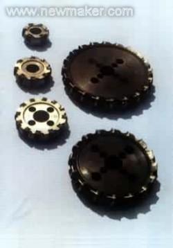
a.Carbide indexable insert face milling cutter b. 苞米棒-type carbide indexable insert end mill Figure 5 Indexable milling cutter
Milling cutters are divided into two categories according to the processing method of the back of the tooth. 1 Conduit milling cutter: Grinding a narrow blade on the back to form the back angle. Due to the reasonable cutting angle, its life is higher. The back of the knives has three straight lines and fold lines (Fig. 6).
Figure 6 The shape of the back of the pitch milling cutter
Linear backs are often used for fine-toothed finishing cutters. Curves and creases have better teeth strength and can withstand heavy cutting loads, and are often used for coarse-tooth milling cutters. 2 shovel milling cutter: the back is processed by the shovel (or shovel) method into the back of the Archimedes spiral. After the cutter is blunt, only the front is regrind, and the original tooth shape can be kept unchanged. For the manufacture of various milling cutters such as gear milling cutters.
This is an external LED emergency converter , it is suitable for external driver LED lamps . Wiring is easy to install and can be hidden in the ceiling . Using good quality aluminum shell cover the whole LED emergency power supply that speed up the heat dissipation . LED emergency module fitted with rechargeable lithium ion battery , it can supply electricity to lamps .

20W Emergency Battery Backup,Emergency Power Supply for Led Light,3.7V Emergency Led Converter
Jiangmen City Pengjiang District Qihui Lighting Electrical Appliances Co., Ltd , https://www.qihuilights.com