Keywords: graphics; CNC cutting; graphics
1 question raised
China's computer application has made great progress in shipbuilding. There is a complete system in the ship structure and electrical calculation. However, with the development of computer application, in order to further improve the shipbuilding speed and shorten the shipbuilding cycle, the existing The hull structure calculation system puts forward higher requirements. On the one hand, it is too cumbersome to use some existing description methods for some hull parts; on the other hand, it is very troublesome to modify the original part description statement and modify it one by one, and then it is very troublesome; Hole work is often carried out after the hull parts have been calculated and set, which is equivalent to starting from the modification of the hull parts, all done again, which is not allowed in time. The system can directly convert the graphics generated by AutoCAI) into the digital cutting code of the CNC cutting machine. In this way, the work is very convenient, very intuitive, and the work efficiency is greatly improved.
2 system composition and implementation methods
The CAD/CAM for the cutting machine consists of three parts, that is, the data extraction of one nesting pattern; 2 the data sorting calculation after extraction, generating the numbering code of EIA format or ESSI format, and calculating various management data information; Screen verification of both codes.
Data extraction for nested graphics is written in the AmoLISP language. It has certain requirements on the drawing of the figure. For example, the inner hole of the hull structure part should be blue, the shape of the structural part should be black, the line on the part should be green, etc., and the different colors can be extracted differently. The data, and the data is stored in different files, the system will automatically display the cutting sequence number and mark at the beginning of the part, the user can adjust the cutting order of the part and change the starting position of the part according to his own wishes.
The extracted data is irregular according to the mapping method and the needs. The system sorts the data according to the shape of the part, and finally arranges the inner hole of the part into a continuous closed clockwise arrangement of spline data.
Similarly, the scribe data should also be organized into reasonable, continuously arranged spline data and then calculate the area of ​​the component, the length of the cut, the length of the scribe line, the utilization of the nesting board, the length of the idling, the weight, and the like. In the computer, each member is scaled to add a cutting compensation amount to make a cutting lead. Generate a cut code in EIA format or ESSI format as needed. This part of the program is written in Visual Basic.
The screen graphics verification program is also written in the AutoL ISP language. It converts the code in EIA format or ESSI format into a graphic display on the screen and restores the graphic to the original graphic color.
3 system design ideas
The overall design idea of ​​the system is shown in Figure 1-3.
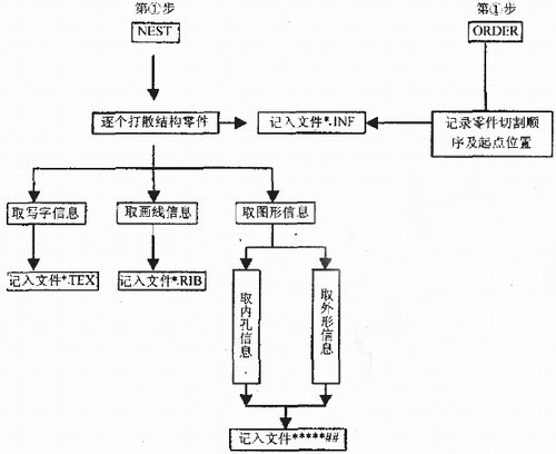
Figure 1 Data extraction block diagram
The implementation of the system mainly needs to solve the following problems.
3.1 Establishment of data files
What data files need to be created. The format of these data files is different, which is often the primary problem solved by the system. Moreover, it also determines the design idea of ​​the system and the processing method of the system to some extent.
The system has the following main documents:
* * * * *.IN F This file is a general information file for a nesting board. It records all part names, sheet sizes, part cutting sequence numbers, and the location of the part cutting start point in the nesting board. This file is automatically generated during system operation. It plays the role of directing the operation of a system. It can mobilize the structural parts according to the user's requirements for the cutting sequence. It is also the basic data for constructing the management database.
* * * * *.RIB This file is a lined data file. The system centrally stores all the lines drawn on one board in this file. The starting point coordinates, the end point coordinates, and the radius of the line segment of each line segment are recorded. If it is a straight line, the radius is zero. The system allows the line to be a straight line, an arc, a full circle or a curve. When the system is running, according to the user's requirements, if you need to scribe, it will first call to process this file.
* * * * *.TEX This file is a data file for writing. The system centrally stores all the words on a board in this file. The position of the writing, the angle of the word, the height of the word, and the text content are recorded. When the system is running, according to the user's request, if you need to write, it will call to process this file.
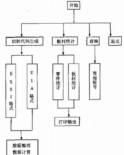
Figure 2 calculation block diagram
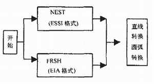
Figure 3 verification program box Yang
* * * * *## This is the data file for each part. The ** * * * in front of the file name is the nesting board number (the file described earlier is the same). Gan# is the cutting sequence number of the part. This file name is not the real name of the part, it has a correspondence with the real part name. This one-to-one correspondence is recorded in the file * * * * *.INF. By designing the file name in this way, the problem that the data of the respective components of the same part name in one board is not covered is solved. In the file, the inner hole data of the part is stored in front, and the shape data of the part is stored later. When the system performs calculation processing, it is taken from the data in these files.
3.2 Data extraction
Extract data from the graph. It is obtained by operating the graphics database according to the method provided by the AutoLISP language. The extracted data is stored in the respective files described above.
3.3 Data sorting
The extracted data can get their starting point coordinates and radius for each graphic unit. However, the elements of the graphic are not necessarily connected end to end, so its original arrangement is likely to be disorganized. The system handles this: it determines whether the end points of the two lines are the same. If they are the same, the positions of the last line are exchanged; the starting points of the two lines are determined to be the same. If they are the same, the previous line will be End point exchange position; determine whether the starting point of the previous line segment is the same as the end point of the next line segment. If they are the same, the starting points of the two line segments are respectively exchanged positions. The system can connect the graphics but the data is not connected to the adjacent data segments. Then, the data is applied together, and according to certain requirements, the spline data arranged in a clockwise or counterclockwise arrangement is arranged.
3.4 Application examples and effects
After the development of the system, a large number of real ship data tests were first carried out before the application was promoted, which was welcomed by the users. The system was used in the 27 000 t ship built in Tianjin Shipbuilding Company. In the past, modifying a part, from modification, calculation, drawing to final completion, took an hour or two and can now be completed in just a few minutes. The work efficiency is obviously improved greatly, and the use effect is very good. Figure 4-8 shows an example of a nesting of the 27 000 t bottom part of Hong Kong.
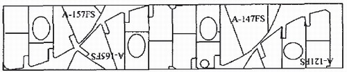
Figure 4 Example of the bottom section of the Hong Kong 270001 ship
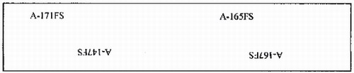
Figure 5 Parts in the nesting diagram should be written in blue

Figure 6 Parts in the nesting diagram are to be green
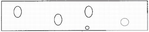
Figure 7 The inner hole of the part in the nesting diagram should be blue
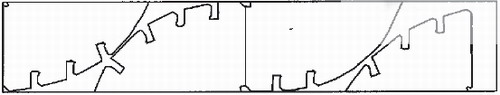
Figure 8 The shape of the part in the nesting diagram should be black
4 Conclusion
The CAD/CAM system described in this paper can be processed in a variety of ways, such as: AutoCAD drawing can be generated by hand, or CAD graphics generated by a shipbuilding system. The system is equipped with EIA format and ESSI format, but for other various cutting machines, it can be easily changed according to its cutting code requirements.
Hydraulic Accumulator,Water Jet Accumulator,Pressure Accumulator,High Pressure Accumulator
Foshan Hairan Machinery And equipment Co.,LTD , https://www.hairannozzle.com