The V-belt (see Figure 1) produced by our company uses a conical fit with the generator to transmit torque with a flat key. The advantage of the conical fit is that it can be self-centering, so that the axes of the two can achieve higher concentricity requirements, but processing and inspection are difficult.
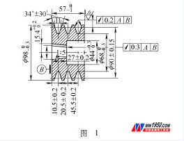
After machining the keyway, the taper keyway depth was originally measured by the vernier caliper to measure the size of the taper tip to the keyway. The error of this detection method is too large. The reason is that the taper hole tip diameter is difficult to measure with the vernier caliper. The maximum diameter of the cusp is not detected, and the measured value error is too large.
Later, after analysis, since the error of measuring the cusp is large, how to avoid the measurement of the point, change to the measurement between two lines or planes?
As we all know, the cone diameter and angle of the cone parts will produce errors during the manufacturing process, the cone diameter error will affect the distance of the base surface when the cone is combined, and the cone angle error will affect the cone bonding property. In order to accurately combine and interchange the cone parts, the diameter and angle error of the cone should be checked.
Measuring the diameter of a part with a cone gauge is based on whether the end face of the part being measured is between the two limits of the gauge to determine whether the cone diameter is satisfactory. The cone angle 2α was examined by the coloring method. The coloring cone gauge is shown in Figure 2.
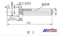
The tapered hole is complemented by using a colored cone gauge, so that the keyway depth can be measured to measure the distance between two parallel planes, which greatly reduces the measurement difficulty. It can be easily measured using a vernier caliper. Since the measured dimensions are converted to the distance between the two planes and the design size of the pattern is different, the dimensions of the two planes of the keyway must be calculated. The calculation process is as follows:
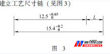
Establish a process dimension chain (see Figure 3)
Calculate closed ring dimensions and tolerances
Basic size L 0 =15.4mm-12.5 mm =2.9 mm
Upper deviation ES 0 = +0.2 mm -0 mm = +0.2 mm
Lower deviation EI 0 =0 mm -(+0.05) mm =-0.05 mm
So the keyway face size is 
Limit size of the closed loop
Maximum limit size L 0max = L 0 + ES 0 = 2.9 mm +0.2 mm = 3.1 mm
Minimum limit size L 0min = L 0 + EI 0 = 2.9 mm -0.05 mm = 2.85 mm
Vertical distance between two planes of the keyway
The tapered taper is 1:5 and the half angle is 5°42'38†(5.711°).
Maximum limit size L max = L 0max cos5.711° = 3.1 mm × 0.995 = 3.085 mm (minimum entity)
Minimum limit size L min = L 0min cos5.711°=2.85 mm×0.995=2.836 mm (maximum entity)
The colored cone gauge is placed in the V-belt taper hole, and the keyway size is measured using a vernier caliper as long as the measured value is within the range of 2.836 to 3.085 mm. In order to improve the efficiency of the detection, the plug is designed to replace the vernier caliper. According to the size of the opening and closing ends of the GB/T1957-2006 plug, the calculation is as follows:
Tolerance of keyway dimensions T= L max -L min =3.085 mm -2.836 mm =0.249 mm
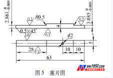
According to IT14 rounding to 0.25, the dimensional tolerance of the plug is shown in Figure 4. The lookup table shows T 1 = 0.009 and Z 1 = 0.020.

Maximum limit size of the end T max = L min +Z 1 +T 1 /2=2.836 mm +0.020+0.009/2=2.861 mm
Therefore, the size of the end of the plug is  , the size of the terminal is
  . The plug pattern is shown in Figure 5.
In production, the plug and the colored cone gauge are used together to detect the depth of the taper hole, which is convenient, fast and reliable. Through the first identification of the product and the verification of the actual production, it can fully meet the design requirements of the product. The problem of inaccurate measurement of the taper keyway depth is solved, and the measurement efficiency is improved.
Globe Valves and angle valves are designed for throttling or regulating flow in commercial and industrial applications. Bronze, cast iron, or cast ductile iron materials. Threaded, flanged, or solder end connections.
Angle valves for use in commercial and industrial applications. Typical services include hot and cold water, HVAC, steam, compressed air, gas and other general utility services.
Vacuum angle valve is used for turn on or shut off the airflow in the vacuum pipeline, the applicable media is air and non-corrosive gases.
It has two structures, one is angle type and another is a 3-way type within an ISO-KF or ISO-F various flange end pre-pump port.
a) Small diameter (≤DN50) valve body are precision investment casting.
b) Large diameter (> DN50) valve body are molding shaped seamless steel or steel plate.
c) Bellows sealed structure can withstand 150ºCtemperature, metal sealed structure can withstand 450ºCtemperature.
d) Can install on any position to control the airflow in the vacuum pipeline, as an on-off valve purpose
Angle Valves, Angle Globe Valves, Brass Angle Valve, Zinc Angle Valve
ZHEJIANG KINGSIR VALVE CO., LTD. , https://www.kingsir-valve.com