The bootstrap circuit is also referred to as a boost circuit, which uses bootstrap boost diodes, bootstrapped boost capacitors and other electronic components to superimpose the capacitor discharge voltage and the supply voltage, thereby increasing the voltage. Some circuits can raise the voltage to several times the supply voltage. Assume that the switch (triode or mos tube) has been disconnected for a long time, all components are in an ideal state, and the capacitor voltage is equal to the input voltage. In order to help you further understand the working principle of the booster circuit , the following points I have to charge and discharge the two parts to illustrate this circuit, I hope everyone read the following description, can have a new understanding of the working principle of the booster circuit .
Boost circuit works
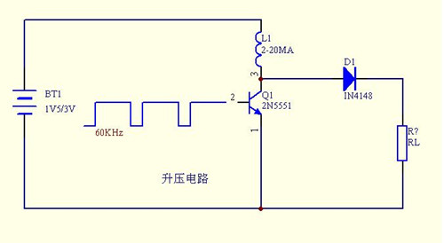
To give a simple example: There is a 12V circuit, the circuit has a field effect tube needs 15V drive voltage, how to get out of this voltage? It is using bootstrapping. Usually a capacitor and a diode are used. The capacitor stores the charge and the diode prevents the current from flowing backwards. When the frequency is high, the voltage of the bootstrap circuit is the input voltage of the circuit plus the voltage on the capacitor, which acts as a boost.
The bootstrap circuit is just a name given in practice and does not have this concept in theory. The bootstrap circuit is mainly used in Class A and B single-supply complementary symmetry circuits. Class A and B single-supply complementary symmetry circuits can theoretically make the output voltage Vo half of Vcc, but in practical tests, the output voltage is as much as less than half of Vcc. One of the important reasons is the need for a voltage higher than Vcc. So use the bootstrap circuit to boost.
Commonly used bootstrap circuits (taken from Fairchild, User's Manual AN-6076, Guidelines for Design and Use of Bootstrap Circuits for High-Voltage Gate Driver ICs)
The principle of the switching DC boost circuit (the so-called boost or step-up circuit) principle is the boost converter, or step-up converter, which is a kind of switching DC boost circuit, which can be higher than the input voltage.
Assume that the switch (triode or mos tube) has been disconnected for a long time, all components are in an ideal state, and the capacitor voltage is equal to the input voltage. The following two parts to charge and discharge to illustrate this circuit.
Boost circuit charging process
In the charging process, the switch is closed (triode conduction), the equivalent circuit is shown in Figure 2, and the switch (triode) is replaced by a wire. At this point, the input voltage flows through the inductor. The diode prevents the capacitor from discharging to ground. Since the input is a direct current, the current on the inductor linearly increases at a certain rate, which is related to the size of the inductor. As the inductor current increases, some energy is stored in the inductor.
Boost circuit discharge process
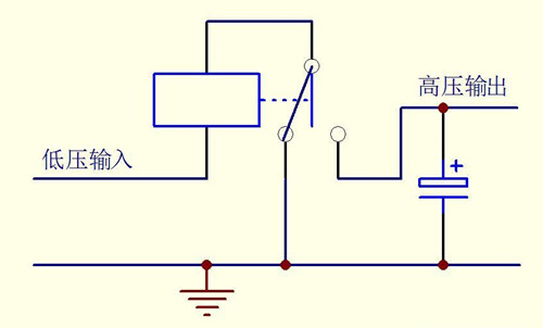
When the switch is turned off (triode cut-off), the current flowing through the inductor does not immediately become 0 due to the current-holding characteristic of the inductor, but slowly changes from the value at the time of completion of charging to zero. The original circuit has been disconnected, so the inductor can only be discharged through the new circuit, that is, the inductor starts to charge the capacitor, and the voltage across the capacitor increases. At this time, the voltage is higher than the input voltage. Boost is complete.
The boosting process is an inductive energy transfer process. When charging, the inductor absorbs energy, and the inductor discharges energy when discharging. If the capacitance is large enough, a constant current can be maintained during the discharge at the output. If this on-off process is repeated, voltages higher than the input voltage can be obtained across the capacitor.
P-Channel High Side Gate Driver
Direct Driver: For a maximum input voltage less than the device's gate-source breakdown voltage.
Open collector: The method is simple, but it is not suitable for directly driving MOSFETs in high speed circuits.
Level-shift drivers: Suitable for high-speed applications that work seamlessly with common PWM controllers.
N-Channel High Side Gate Driver
Direct Driver: The simplest high-side application for MOSFETs, driven directly by a PWM controller or a ground-referenced driver, but it must meet the following two conditions:
VCC Floating Power Gate Drivers: The cost impact of an independent power supply is significant; optocouplers are relatively expensive, have limited bandwidth, and are sensitive to noise. Transformer-coupled drivers: Full control of the gate over an indefinite period of time; but to a certain extent, the switching performance is limited. However, this can be improved, but the circuit is more complicated. Charge pump drivers: For switch applications, the on-time is often very long; due to the low efficiency of the voltage multiplication circuit, more low-voltage-grade pumps may be needed. Bootstrapped drivers: simple, inexpensive, and limited; for example, the duty cycle and on-time are limited by the bootstrap capacitor. Need level shifting, and related issues. Editor's summary: The above is a brief introduction to the working principle of Boost Boost Circuit. Hopefully it will help friends who have this need! For more information, please continue to pay attention to our website, follow-up will show more exciting content. Siphon principle Refrigeration principle Boost circuit working principle Our Water Pump Bearing is good in quality and competitive in price. We are manufacturer and supplier of Water Pump Bearing following your specific requirement. We are looking forward to your
E-mail and establishing cooperative relationship with you! We would
provide professional Water Pump Bearing with good services for you! Water Pump Bearing, Automotive Water Pump Bearings, Water Pump Shaft Bearing Ningbo Borine Machinery Co.,Ltd. , https://www.borine-agroparts.com