1 Overview
This technical specification stipulates the environmental conditions, basic parameters, technical requirements, inspection rules, and acceptance specifications for 500 kW photovoltaic grid-connected inverters (hereinafter referred to as photovoltaic inverters).
This technical specification applies to the manufacture, ex-factory inspection and acceptance of a 500 kW photovoltaic grid-connected inverter (hereinafter referred to as PV inverter).
2 Reference standards
GB/T 191-1990 Packaging, Storage and Transportation Icon Standard
GB/T 3859.1-93 Basic Requirements for Semiconductor Converters
GB/T 3859.2-93 Semiconductor Converter Application Guidelines
GB/T 3859.3-93 Semiconductor converter transformers and reactors
GB/T 12325-2008 Power quality supply voltage deviation
GB/T 12326-2008 Power quality voltage fluctuations and flicker
GB/T 14549-1993 Power Quality Public Power Harmonics
GB/T 15543-2008 Power Quality Three-Phase Voltage Allow Unbalance
GB/T 15945-2008 Power Quality Power System Frequency Deviation
GB/T 18481-2001 Temporary overvoltage and transient overvoltage in power quality
GB/T 13422-1992 Semiconductor power converter electrical test method
GB/T 18479-2001 Overview and Guidelines for Photovoltaic (PV) Power Generation Systems for Ground Use
GB/T 19064-2003 Technical requirements and test methods for domestic solar photovoltaic power systems
GB-Z 19964-2005 Technical Requirements for Photovoltaic Power Plant Access to Power Systems
GB/T 19939-2005 Photovoltaic system grid connection technical requirements
GB/T 20046-2006 Photovoltaic (PV) System Grid Interface Features
CNCA/CTS 0004-2009 Technical Requirements and Test Methods for Low-Voltage Grid-Connected Photovoltaic Power Inverters Below 400V
3 use of environmental conditions
The environmental conditions for the use of photovoltaic inverters are shown in Table 1.
Table 1 Using environmental conditions
No. | Items | Site conditions |
1 | Installation Location | indoor |
2 | Altitude | <1000m |
3 | Ambient temperature | - 10 °C to + 45 °C |
4 | seismic intensity | 8 degrees |
4 basic parameters
The basic parameters of the photovoltaic inverter are shown in Table 2.
Table 2 Basic parameters
No. | project name | parameter | Note |
1 | Maximum DC input voltage (V) | 850 | |
2 | Input voltage range MPPT(V) | DC450~820V | |
3 | Rated output power (kW) | 500 | |
4 | Rated output voltage (V) | AC380 | No isolation transformer |
5 | Rated output frequency (Hz) | 50 | |
6 | Rated power factor | 0.99 | |
7 | Rated efficiency | 0.98 | |
8 | Current total harmonic content (THD) | <5% | |
9 | Noise (dB) | ≤ 65 | |
cooling method | Forced air cooling |
5 Technical requirements
a) Output voltage variation range: ±10% of the rated value should not be exceeded;
b) Output frequency range: The PV inverter shall run synchronously with the grid, and the output frequency deviation shall not exceed ±0.5 Hz;
c) The output voltage waveform distortion rate and harmonics meet the requirements of the national standard GB/T14549-1993 "Power Quality - Harmonics in Public Grids";
d) The three-phase unbalance of the output voltage meets the requirements of the national standard GB/T15543-2008 "Power quality - Three-phase voltage permissible unbalance";
e) DC component
In grid-connected operation, the DC current fed from the PV inverter to the grid should not exceed 0.5% of the inverter's output current rating.
f) Power Factor Requirements: When the PV inverter output power is greater than 50% of the rated output power, the lagging power factor should not be less than 0.98;
g) load capacity
1) When the input voltage and output power are rated values ​​and the ambient temperature is 25°C, the continuous reliable operating time of the PV inverter shall not be less than 4 hours;
2) When the input voltage is rated and the output power is 125% of the rated value, the safe working time of the PV inverter shall not be less than 1min;
3) When the input voltage is rated and the output power is 150% of the rated value, the safe operating time of the PV inverter shall not be lower than 2s;
h) Has maximum power point tracking (MPPT) and soft start functions;
i) Dielectric properties: Meet the voltage withstand voltage requirements of the insulation;
j) Protection performance: PV inverters shall have overvoltage/undervoltage protection, overfrequency/underfrequency protection, overcurrent protection, short circuit protection, reverse polarity protection, restoration of grid connection, back-discharge protection, island effect protection, etc. .
k) Communication interface requirements: Profibus-DP fieldbus communication interface;
l) Cabinet Requirements
1) The cabinet adopts a self-supporting structure installed on the vertical ground, and the hoisting interface is reserved, and there is a protective grounding.
2) The cabinet adopts the cable into the line, the DC side is set to the line terminal, the capacity meets the rated current requirement, and the positive and negative busbars each have at least 5 DC cable input terminals; the AC side sets the outlet copper bar, capacity Meet rated current requirements, leaving no less than three outlet terminals for AC cables in each phase.
3) Protection class: IP23.
6 Inspection Rules
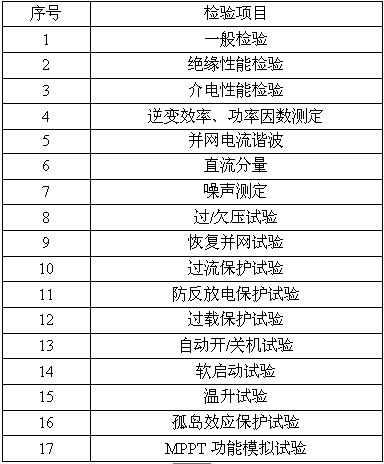
The equipment inspection is factory inspection and field test items. The factory inspection items are shown in Table 3.
Table 3 Factory inspection items
Acceptance of equipment according to the factory test and field test project acceptance.
7 Colours, nameplates and signs
7.1 Color
The color of the outer surface of the device is provided by the buyer.
7.2 Nameplate
The nameplate is made of stainless steel, the writing is not easy to wear out throughout the life, the fasteners of the nameplate must not penetrate the chassis;
Nameplate type, specifications and other requirements in accordance with the relevant provisions of GB/T 13306.
7.3 Signs
The indication of grounding shall be provided near the location of the equipment's grounding bolt.
Terminal markings shall comply with the relevant provisions in GB 1971;
8 Others
8.1 Random Files
The drawings and documents provided are:
a) packing list;
b) product leaving the factory certificate;
c) factory test report and type test reports of such products;
d) Installation, operating instructions, technical specifications, electrical schematics, cabinet installation wiring diagram, terminal layout, etc.;
e) Provide the required clearances for operation and maintenance of the equipment installation, installation dimensions, control cables, power cable inlet locations and connection details;
f) Main technical data and installation structure diagram;
g) total equipment weight, maximum transport size and weight;
h) Installation instructions, commissioning instructions, operation manuals, maintenance manuals, parts catalogs, etc.
8.2 Quality Assurance Period
The warranty period is not less than 2 years after the formal acceptance of the equipment.
Measuring wheel also called mechanical ranging car or digital distance measuring wheel.it is widely used to measuring distance in professional surveying and mapping work,road engineering, landscape planning and design,golf course and lanes ect.
The instruction of digital measuring wheel
Please read this instruction before you use the product
Thanks you for choosing our product. This instrument is a new length measuring instrument, it is easy to use,stable and reliable.
The main features:
You could convert the unit between metric and foot; The data could be stored and extracted; The touch switch of the digital measuring wheel is anti-water; The handle which could adjust the height of the instrument is easy to apply. The wheel wrapped with rubber could help to avoid slipping so that the measuring data is more precise.
1.The main parts (From up to down):
Handle
Data display panel
Battery cover
Handle lock
Measuring wheel
Kickstand
2. Technical data:
A. It could measure up to 99999.9m/ft.
B. Accuracy:+/- 0.3%
C: Minimal display :0.1m
D: Power supply 3V (2xAAA LR003)
E: Suitable temperature for use : -10c°~45c°
3. Button and Operation
CLR: Clearance
SM : Store the data
ON/OFF: Switch
Rm: Extra the data
M/ft: Conversion between metric and foot
Data display panel
Power supply
The stored data
The displayed data
Metric
Foot
1. ON/OFF : Switch.
2. m/ft: it means the conversion between metric and foot. If you select (m), the displayed data is based on metric. If you select (ft) ,the displayed data is based on foot.
3. SM: Store the data. You could save the data that shows on the display panel by pressing this button. It could store 5 records that respectively show on M1, M2,M3, M4, M5.( Refer to Table 1)
Before storing After storing Full of the memory
(Table 1)
4. RM: Extract the stored data from SM. For example, if you have already stored the measuring data 5M as M1, 10M as M2. But now the measuring data is 120.7M, you could press the bottom RM once then the digital display panel will shows the the data of M1. The top right of the display panel shows [R". The data of the digital display panel will return to the present data after two seconds. ( Refer to Table 2). If you press the RM twice, the data of the M2 will show on the display panel, the [R" also is on the top right. The data of the digital display panel will return to the present data again after two seconds.
Present data Press the RM Once After 2 seconds
(Table 2)
Present data Press the RM twice After 2 seconds
(Table 3)
5. CLR: Clearance. Once you press this button, the present data will be deleted.
4.Precautions for use
Please open the handle lock to adjust the suitable height of this instrument at first and then close it before using the instrument. Put away the kickstand and turn on the power. Put the wheel on the road to be measured when the data is 0.0m on the digital display panel. Please press the bottom CLR if you want to delete the present data.
1. Please go straight if you want to measure a straight line to ensure the accuracy of the measurement.
2. Do not measure uneven surfaces because it will reduce the accuracy.
3. Do not measure in the rain for a long time.
4. Do not use the instrument under the high temperature environment or keep this product in the high temperature place.
5. Please open the battery cover by using the cross-head screwdriver and change the battery when the digital display panel is dark.
6. Do not deal with the used batteries by yourself, please send them to the government designated place where to recycle them.
7. Please remove the battery and clean the instrument by use the mild detergent to prevent rust if you haven`t used it for a long time. Then please pack it well and save it in the rough place.
8. Do not use benzene solution to clean the instrument, otherwise its surface will be corroded.
9. Do not use this the instrument as a toy for child for avoiding unnecessary damage.
Measuring Wheel,Measuring Wheel Walking,Wheel Measuring Tool
Wintape Measuring Tape Company , https://www.wintapetapemeasure.com