Abstract: The PID adjustment instrument is used together with the sensor to measure and display the temperature of the hood furnace on the steel product production line. Through the corresponding actuators, PID adjustment and control, alarm control, data acquisition and recording of the relevant hood furnace equipment can be realized. However, for a field environment with multiple production lines and multiple PID adjustment instruments for each production line, it is not convenient to operate each instrument in turn. An online centralized monitoring system for PID regulating instruments was designed using Borland C++ Builder 6. Using Borland C ++ Bu ilder 6 powerful graphical control interface, and SPComm control programming under serial port, through USB to RS485 protocol converter, real-time monitoring of real-time monitoring of various partition instruments on the production line remote control.
1 Introduction
In the steel product manufacturing enterprise, for the on-site environment with multiple production lines and multiple PID adjustment instruments for each production line, if each instrument is operated in turn, the parameter design of the instrument and the temperature monitoring of the hood furnace equipment will be made. It becomes more complicated, which not only affects the efficiency of meter adjustment, but also affects the real-time performance of meter adjustment.
In order to effectively realize real-time monitoring and remote control of the instrument data of each zone on the production line, Borland C ++ Bu ilder6 was used to design a centralized monitoring system for PID regulating instruments through USB to RS485 protocol converter. It mainly includes: temperature monitoring system for hood furnace equipment on steel production line, database system, and reading and writing data system for PID regulating instrument.
2 Overall structure of the monitoring system
The monitoring system adopts the RS485 bus structure, and realizes the network communication between the host computer and the PID regulating instrument through the U SB to RS485 protocol converter. The RS485 bus is characterized by simple and convenient implementation. It can be networked to form a distributed system through RS-485. It allows up to 32 drives and 32 receivers to be connected in parallel, which can fully meet the networking needs of multiple PID adjustment instruments on the production site.
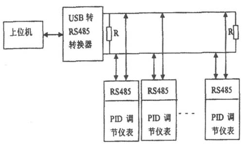
Figure 1 Overall structure of the monitoring system
3 monitoring system hardware design
3. 1 self-tuning expert PID adjustment instrument
The self-tuning expert PID adjustment instrument has a wide switching input of 100 ~ 240VAC input. The input adopts digital calibration and self-calibration technology, the measurement is accurate and stable, and the measurement error caused by temperature drift and time drift is eliminated. The instrument adopts the surface mount technology and adopts multiple protection and isolation design, which has strong anti-interference ability and good reliability.
The instrument adopts advanced expert PID intelligent adjustment algorithm, which is precise and stable in control, without overshoot, and has high precision self-tuning (AT) function.
The instrument output is designed with a modular hardware structure, and multiple control modes can be realized by replacing different functional modules. PID control output can choose 4mA ~ 20mA current, (1V ~ 5V voltage), SSR drive, single-phase / three-phase SCR zero-crossing trigger and single-phase SCR phase shift trigger, etc., and two alarm output functions, Optional transmission output, or standard communication interface (RS485 or RS232).
The meter has multiple types of input functions, and one meter can be connected with different input signals (thermocouple/thermal resistance/linear voltage/linear current/linear resistance), which greatly reduces the number of tables. It has a wide range of applications and can be used with various sensors and transmitters to measure and display physical quantities such as temperature, pressure, liquid level, capacity, force, etc., and with various actuators for electric heating equipment and electromagnetic, The electric valve performs PID adjustment and control, alarm control, data acquisition and recording.
3. 2 USB to RS485 protocol converter
USB to RS485 protocol converter is a plug-and-play protocol converter, fully compatible with U SB (Universal Seria l Bus) Rev: 2. 0; supports any baud rate, data bit, stop bit, data transmission and reception time Parameters such as interval are an adaptive protocol converter.
Support RS-232/485 interface, data transmission rate above 2Mbps.
Support automatic handshake protocol; Support remote wake-up and power management; Support USB bus to directly take power, no external power supply (DC 5V); Driver is confirmed twice, the first is chip driver, the second is I / O port driver , can be completed for the driver in the same directory.
4 Software design of the monitoring system
The software system of the monitoring system is designed and developed by Borland C++ Builder 6. Through its powerful graphical control interface and SPComm control programming under the serial port, Modbus protocol is adopted, and the RS485 protocol converter is realized by USB. The communication function between the upper computer and the PID adjustment instrument can conveniently realize the parameter monitoring and remote operation control of each regional instrument on the production line through the operation of the interface of the upper computer monitoring system.
The software system mainly consists of three parts: the temperature monitoring system of the hood furnace equipment on the steel product production line, the database system, and the read-write data system of the PID adjustment instrument.
4. 1 Modbus communication
The standard Modbus port uses an RS-232C-compatible serial interface that defines the pin, cable, signal bits, baud rate, and parity of the connector. The controller can be networked directly or via a modem.
The controller communicates using a master-slave technique, ie the master can initiate a transfer (query). The slave responds based on the data provided by the master device query. Each Modbus frame includes an address field, a functional domain, a data domain, and an error detection domain, regardless of whether the primary device queries or the slave device responds. Modbus communication has two modes: ASC II mode and RTU mode. Compared to ASC II mode, RTU mode can transfer more data than ASCII mode at the same baud rate.
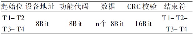
With the RTU mode, the message transmission must start at least at a pause interval of 3.5 characters. The entire message frame must be transmitted as a continuous stream. If there is a pause of more than 1.5 characters before the frame is completed, the receiving device will refresh the incomplete message and assume that the next byte is the address field of a new message. Similarly, if a new message begins with a previous message less than 3.5 characters, the receiving device will consider it a continuation of the previous message. This will result in an error because the value in the last CRC field may not be correct. A typical message frame is shown in Table 1.
Table 1 RTU message frame
The PID adjustment instrument adopts Modbus-RTU mode for upper computer communication. The protocol format is: 8 data bits, 1 stop bit, no parity bit, and the transmission and reception data are all in hexadecimal format.
The format of the transmission data is shown in Table 2.
Table 2 Send data format
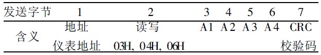
Wherein, when the communication address of the parameter is expressed by one byte, it corresponds to the A2 position, and A1 defaults to 00H; the 03 and 04 instructions are all read commands, wherein the data corresponding to the 04 reading is not writable, and the 03 and 06 commands correspond to the parameter address. One read, one write; A1, A2 and A3, A4 form two double-byte data, CRC check code is a double-byte data, all data are high first and low low; 03. When the 04 instruction reads data, A 1 and A2 are the addresses to start reading, A3 and A4 are the numbers of consecutive reading data. In the 06 command, A1 and A2 need to write the address of the data, and A3 and A4 indicate that The data written.
Return data format, 06 When the instruction writes data, the transmission is consistent with the returned data; 03, 04 instruction returns the data format as shown in Table 3, where the number of returned data bytes is: N × 2.
Table 3 returns the data format

4. 2 temperature monitoring system
The temperature monitoring system is designed and developed by Borland C ++ Builder 6. It mainly involves the use of controls such as Chart, T imer, SPComm and Ma inM enu. System programming mainly includes: sampling program, data saving program, backup history data program, etc. The main process of the temperature monitoring system is shown in Figure 2.
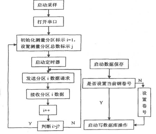
Figure 2 Main flow chart of the monitoring system
4. 3 database system
Start the database system program, first select the corresponding database file, the corresponding database information will be displayed, as shown in Figure 3. The database system mainly includes two data retrieval methods: Mode 1, search by selecting the retrieval date; Mode 2, setting the volume number, and searching by volume number. Through the database system, browsing and querying of historical data can be conveniently implemented.
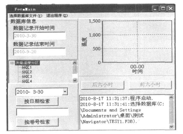
Figure 3 database system
4. 4 PID adjustment instrument read and write data system
The PID read/write data system mainly includes three functions: data setting function before writing to the meter, data writing function and reading instrument data function.
Figure 4 shows the main flow chart of the data writing instrument program. The data setting function is mainly implemented in two ways: Route 1, add the system configuration setting file “MControliniâ€, and set and modify the temperature and time parameters in the configuration setting file to realize the setting operation before the data is written into the instrument; 2, start the read and write data system program, select the corresponding database file, the system program will automatically associate the total number of partitioned meters set in the database file, through the modification and setting of the temperature and time parameters of each curve segment of each partition, realize data writing Setting operation in front of the meter. Wherein, when the route 2 sets the data, the format and size of the input data can be judged, and the reset data state change will be correspondingly displayed in the curve segment corresponding to the interface in real time.
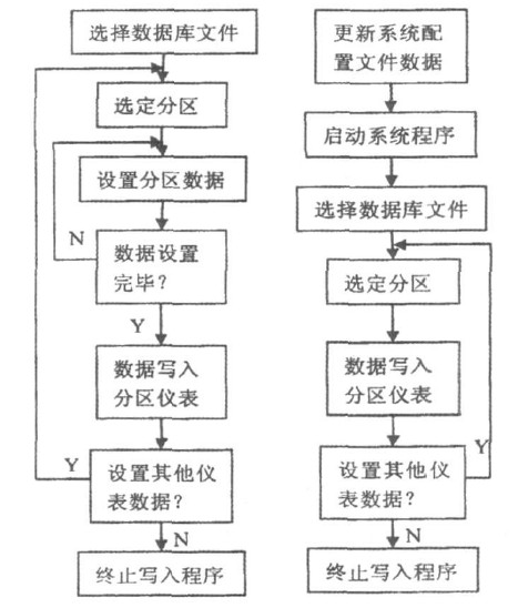
Figure 4 main flow chart of data writing instrument program
Figure 5 is the main flow chart of the reading instrument data program. By comparing and analyzing the instrument data read by the system with the parameters in the system configuration file, it is determined whether the instrument data is consistent with the system configuration file data.
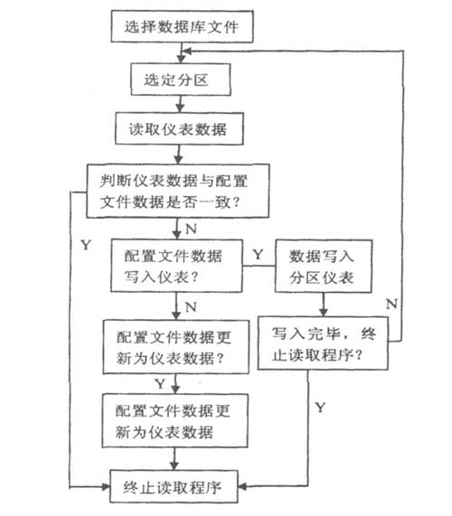
Figure 5 main flow chart of reading instrument data program
If “Yesâ€, it indicates that the parameters set by the system are in good agreement with the meter data, and the reading program is terminated; if “Noâ€, the next step of the program is executed: “Profile data is written to the meterâ€, or “Configuration†The file data is updated to meter data." By reading the meter data program, the system achieves the consistency of the profile data and the meter data.
5 Conclusion
The distributed system formed by RS485 bus can meet the networking requirements of multiple PID regulating instruments. Based on the RS485 bus structure, the monitoring system designed by Borland C + + Bu ilder6 is used to realize the real-time monitoring and remote control of each partition instrument on the production line through the Modbus protocol, which brings a good practical to the production of related enterprises. Benefits, saving a certain amount of human resources and production costs, have certain practical significance.
references:
[1]. RS485 datasheet http://
[2]. RS232 datasheet http://
Aluminum Alloy Spinning Lighting Pole
The spinning pole is the use of foreign advanced spinning equipment,forming a whole without welding,forming a conical or profiled bar.And then polishing,remove surface oil,burr and indentation.Then after the quenching intensity,to T6 state,in line with international standards.The product never rust ,strong corrosion resistance,diversified surface treatment process,the appearance of simple fluid lines.Light weight and convenient installation and transportation,the rod body can be 100%recycling,low melting temperature.

Product features
â‘ Using spinning equipment advanced,the whole forming a non welding
â‘¡Product permanent does not rust,corrosion resistance
â‘¢Diversified surface treatment technology,make the appearance line succinct smooth
â‘£The light weight,convenient installation and transportation
⑤The rod body can be 100% recycling,melting temperature is low.
Aluminum Alloy Spinning Lighting Pole,Lightest Aluminum Alloy,Aluminum Alloy Torchlight,Lightweight Aluminum Alloy
Jiangsu chengxu Electric Group Co., Ltd , https://www.chengxulightings.com