With the rapid development of the drilling industry, the role of various forms of drilling rigs in economic construction is particularly prominent, and the development level of drilling rigs has received more and more attention. In order to promote the rapid development of drilling rigs, advanced drilling rig design methods are particularly important for the development of drilling equipment. In view of the wide application of parametric design ideas in other mechanical design fields, this paper puts forward the idea of ​​structural parameterization design of drilling rig components based on SolidWorks secondary development technology, and takes the core drilling chuck design as an example to give a detailed method. Introduction, the final realization of the parametric design and assembly of the chuck parts. The results show that this method is an effective rig structure design method, which improves the design efficiency and saves cost, and has certain reference significance for the design of other parts of the rig.
1 parametric design method
Parametric design refers to obtaining the required part or assembly drawing by modifying the model parameters based on the existing model. There are many parametric design methods based on the secondary development of SolidWorks. The most convenient way is to obtain the operation code through the recording macro tool provided by SolidWorks, copy it into the Visual Basic program code, and then edit and modify to meet the program design requirements. The model creation and update is done by driving the design variable size. The design of the chuck in this paper adopts this method. The essence is to transfer the dimensional parameters in the SolidWorks series part design table in the software compiled by the visual programming language Visual Basic, and convert these parameters into the specific parameters of SolidWorks 3D solid modeling. To build the corresponding model.
2 SolidWorks Series Parts Design Table Application Overview
The SolidWorks Series parts design table is widely used in the serial design of parts of the same structure and different sizes. Due to the different diameters of the core drill rigs, the components of the chuck have the same structure, but the external dimensions have obvious series differences. These parts with the same structure and different sizes can be formed into parts by the function of the SolidWorks series parts design table. The library uses the part design table to drive the part model to achieve rapid design of the series of parts. The SolidWorks series part design table is interconnected with Office Excel software. Through the operation of the series part design table, the operation of the part size and the relationship between the dimensions of the parts can be realized. The specific process is to first insert a new, blank series part design table in the model, and then input the series part design table information directly in the work table. When the input series part design table information is completed, the new configuration will be automatically generated in the model.
2.1 Insert a new series of parts design table
Click Insert, New Series Design Table on the toolbar. An embedded worksheet appears in the window and the Excel toolbar replaces the SolidWorks toolbar. In the PropertyManager: First under Source, select Blank to insert a blank series design table. Then under Edit Control, select Block to edit the model that will update the series design table so that if these changes will update the series design table, the model will not be allowed to change. Finally, under Options, the number and the new configuration are cleared so that any changes made to the model will not update the series design table, and the Excel toolbar will replace the SolidWorks toolbar.
2.2 Edit Series Design Table
After you open the series parts list, you have to edit it.
a. Dimensions Double-click a dimension in the graphics area to insert a new series of parts design tables and make sure all necessary dimensions are displayed). The Size @Feature or Size @ Sketch parameter is now inserted into the cell.
b. Feature Compression Double-click on a face of the feature, at which point the $state@feature parameter is inserted into the cell.
c. Component Compression Double-click on one face of the component and the $state@component <instance> parameter is inserted into the cell. When you continue to increase parameters in this way, adjacent cells (C2, D2, etc.) are automatically activated. Each parameter is added to the header row and the current value is displayed in line 3 (first instance).
d. Enter the name of the configuration you want to generate in column A. The name cannot contain a forward slash (/) or (@) character.
e. In the trial table cell, enter the parameter value, taking Kava as an example. Figure 1 is the kava series parts list designed in this paper.
Kava series parts design table
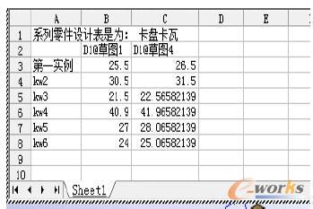
Figure 1 Kava series parts design table
To display the configuration added by the series design table, click the ConfigurationManager tab at the bottom of the window. Double-click the name of the configuration, or right-click on the name and select Show Configuration, as shown in Figure 2.
Chuck kava configuration diagram
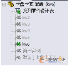
Figure 2 Chuck slip configuration diagram
3 Parametric design examples of drilling rig parts - one parameterized design of chuck
The chuck is an independent and important component of the core drilling rig. It is generally composed of a clamping element, an intermediate force transmitting mechanism and a clamping power unit, including a slip, a slip seat, a collar, a disc spring, and an oil pump loop body. , outer casing, upper cover and base. In this paper, the various components of the chuck are parameterized, but the kava, the slip seat and the chuck assembly are taken as an example for detailed introduction.
3.1 Automatic calculation of basic parameters of the chuck
The calculation of the basic parameters of the chuck is the premise of the parameterized design of the entire chuck. The basic parameters of the chuck mainly include the maximum load and the equivalent clamping force. According to the calculation formula of the basic parameters of the chuck, the basic parameters of the chuck are automatically calculated by using Visual Basic. The user interface, under the input of known conditions, can get the basic parameters of the chuck.
3.1.1 Maximum load Pmax
Under strong lifting conditions, the chuck load is:
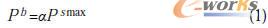
Where a is the safety factor, taking 1.25 to 1.6; Psmax is the maximum top force of the feed mechanism.
Under normal working conditions, the chuck load is:
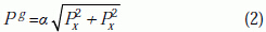
Where Px is the axial force acting on the drill pipe, taking the maximum plus (subtraction) pressure feed force; Py is the circumferential force acting on the drill pipe, Py = 2Mn / d, where Mn is the sub-low speed output of the gyrator Torque, d is the diameter of the drill pipe.
The above two values ​​are compared, and the largest one is the maximum working load Pmax, that is, Pmax=max{Pb, Pg}.
3.1.2 equivalent clamping force
The equivalent clamping force Q is the clamping force necessary for the chuck to withstand the maximum load P:
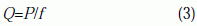
The middle factory is the friction coefficient between the slip and the drill pipe, f=0.3~0.5.
Combined with the relationship between the above parameters, the basic parameter calculation program flow of the chuck is designed as shown in Figure 3. The corresponding visualization program is written by Visual Basic, and the basic parameters of the chuck can be obtained under the input of the necessary known conditions. .
Basic parameter calculation program flow chart of the chuck
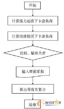
Figure 3 Flow chart of the basic parameters calculation program of the chuck
3.2 Parameterized design of slip structure
The core rig is generally used in the kava type hydraulic chuck. The slip type hydraulic chuck transmits the axial force and torque by the friction generated by the contact surface between the slip and the drill rod under the positive pressure. The size is closely related to the diameter of the drill pipe, so the choice of the size of the slip depends mainly on the diameter of the drill pipe. The specific parameterization design steps are as follows.
a. In SolidWorks, based on the structural characteristics of the chuck slip, a three-dimensional solid model of the slip with a diameter of 51 mm is established (Fig. 4).
Chuck kava structure
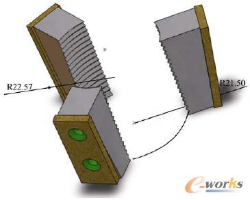
Figure 4 Chuck slip structure
b. While creating the kava 3D solid model, use the secondary development technology in SolidWorks, that is, the method of recording macros, open the recording macro operation in SolidWorks, and obtain the macro operation code.
c. According to the relationship between the size of the slip and the diameter of the drill pipe, apply the SolidWorks part design table method to create the kava series part design table under different drill pipe diameter conditions. Figure 1 shows the standard drill pipe diameters of 51mm, 61mm, 43mm. , 81.8mm, 54mm, 48mm case Kava series parts design table.
d. After the recording is finished, add the macro operation code copy to the corresponding part of the Visual Basic program code, and then edit and modify the debug to achieve the program requirements. At the same time, use Visual Basic to write the kava structure parameterized design program, and the user who compiles with Visual Basic will be compiled. The interface links to SolidWorks.
The parameterization design flow of the entire slip structure is shown in Figure 5. The kava structure parameterization program is run, and different kava structure diagrams can be obtained when different drill pipe diameters are input in the visualization interface.
Kava structure parameterization flow chart
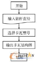
Figure 5 Kava structure parameterization flow chart
3.3 Parameterized design of the slip seat structure
The slip seat is a component that restricts the radial movement of the slip. Its size structure changes according to the size of the slip. The inner diameter of the slip seat is slightly larger than the diameter of the drill pipe, and other sizes vary according to the change of the inner diameter. Similar to the Kava parametric design process, a 3D model of the slip seat with a diameter of 51 mm is built in SolidWorks (Fig. 6), and the macro is operated to obtain the macro code according to the size of the slip seat and the diameter and diameter of the drill pipe. The relationship between the dimensions, the SolidWorks part design table method, create a kava seat part design table with standard drill pipe diameters of 51mm, 61mm, 43mm, 81.8mm, 54mm and 48mm; then add the macro operation code copy to The corresponding part of the Visual Basic program code, edit and modify the debugging to achieve the program requirements; at the same time, use Visual Basic to write the parameterization design program of the Kaval seat structure, link the user interface of Visual Basic compilation with SolidWorks, and run the parameterization program of the Kaval seat structure. Then, when you input different drill pipe diameters in the visual interface, you can get different kava structure diagrams.
3.4 Parameterized design of chuck assembly
The chuck assembly combines various chuck parts such as slips and slips to form a whole body and realize its clamping function. The parameterized design process of the chuck assembly is similar to the parameterized design process of the basic part, as follows.
a. When the diameter of the drill pipe is 43mm, the model of the slip seat corresponding to the slip design series is used as the reference component, and the corresponding other components are coaxially matched according to the position of the slip seat, and the joint faces are adopted between the joint faces. Cooperate, assemble each component one by one. At the same time, before the assembly, open the recording macro operation in SolidWorks to get the macro operation code.
Kava seat structure
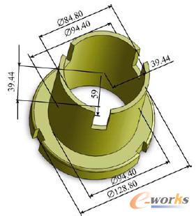
Figure 6 Kava block structure
b. After the macro recording is finished, add the macro operation code copy to the corresponding part of the Visual Basic program code, and then edit and modify the debug to meet the program requirements.
c. Generate assembly configurations for different drill pipe diameters by assembling the individual part design tables for the parts.
d. Use Visual Basic to write the kava structure parameterized design program. At the same time, the user interface generated by Visual Basic is linked with SolidWorks, and the creation and update of the chuck assembly is realized by the program-driven design variables.
By inputting different drill pipe diameters, the system can select different component models and cooperate to automatically generate the final assembly drawing. For example, if the input drill pipe diameter is 43mm, click the assembly button to get the figure shown in Figure 7. A drill chuck structure with a diameter of 43 mm.
Chuck assembly drawing with a diameter of 43mm
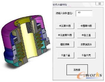
Figure 7 Chuck assembly drawing with a diameter of 43mm
4 Conclusion
Based on the secondary development of SolidWorks, this paper completed the structural parameterization design of the key parts of the core drilling rig. Under the condition of inputting the known parameters on the user interface calculated by the Visual Basic program, the basic parameters of the chuck can be completed. Automatic calculation, in the user interface of the chuck parameterized design, the part structure drawing of the chuck and its total assembly drawing can be generated in the SolidWorks system only by inputting the diameter of the drill pipe, and the parameterized design requirements of the drilling chuck are realized. Through debugging, the system has certain intelligence, and is easy to operate and user-friendly.
This paper applies the parametric design method to the rig chuck design, which is only a new attempt. It provides a reference for the structural parametric design of other components of the rig, and also lays a foundation for the overall parametric design of the rig, thus greatly reducing the number of Designer design time increases design efficiency and saves design costs.
Stainless Steel Handrails Outdoor Steps,Stainless Steel Stair Railing Ideas,Stainless Steel Handrails For Stairs,Stainless Steel Handrail Pipe
Lemon Building Material Co., Ltd. , https://www.lemonbuilding.com