When the centrifugal pump is started, the pump shaft drives the impeller together to perform a high-speed rotary motion, forcing the liquid pre-filled between the blades to rotate. Under the action of the inertial centrifugal force, the liquid moves radially from the center of the impeller to the outer periphery. The liquid gains energy during movement through the impeller, the static pressure increases, and the flow rate increases. When the liquid leaves the impeller and enters the pump casing, it is decelerated due to the gradual enlargement of the flow passage in the casing, and part of the kinetic energy is converted into static pressure energy, and the trailing edge tangentially flows into the discharge line. So the pump casing not only collects the components that flow out of the impeller but it is also a kinetic energy device. When the liquid flies from the center of the impeller to the periphery, the center of the impeller forms a low-pressure zone (which forms a vacuum) and the liquid is drawn into the center of the impeller under the action of the total potential energy difference (differential pressure) between the liquid level of the storage tank and the center of the impeller. With the continuous operation of the impeller, the liquid is continuously sucked in and discharged. The mechanical energy obtained by the liquid in the centrifugal pump eventually manifests itself as an increase in static pressure energy. 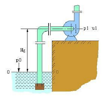
1. What is the treatment method of gas binding and gas binding?
Before the start of the centrifugal pump, the pumped liquid was not filled in the pump casing. Because of the low air density, the centrifugal force generated after the rotation of the impeller is small, and the center area of ​​the impeller is not enough to form the low pressure of the liquid sucked into the storage tank. Thus, the centrifugal pump is started. Can not transport liquids. This shows that the centrifugal pump has no self-priming ability. This phenomenon is called gas-bearing. The suction line installs the one-way bottom valve to prevent the liquid poured into the pump casing from flowing out of the casing before starting. Air from the suction pipe into the pump casing can cause gas to bind. Therefore, the centrifugal pump must be filled with liquid before starting the centrifugal pump, and a bottom valve with a filter screen is installed at the bottom of the suction tube. The bottom valve is reversed to prevent the liquid poured from the pump from leaking before starting. The filter prevents solid matter from entering the pump. A pressure regulating valve is installed near the outlet of the pump to regulate the flow.
Cavitation phenomenon
(1) In the pipeline shown in the figure, there is no external energy between the liquid level 0 - 0 and the section 1 - 1 near the pump inlet, and the liquid flows by pressure difference. Therefore, to increase the installation position of the pump, the pressure at the inlet of the impeller may drop to the saturated vapor pressure of the liquid being transported, causing the liquid to partially vaporize.
In fact, the lowest pressure in the pump is located on the back of the blade on the inner edge of the impeller. When the mounting position of the pump is up to a certain distance, vaporization occurs first and bubbles are generated at the place. After the bubble-containing liquid enters the impeller, the pressure bubble rises and the bubble condenses immediately. The disappearance of the bubble generates a partial vacuum, and the surrounding liquid flows at a high speed toward the center of the bubble, causing shock and vibration. Especially when the condensation of bubbles occurs near the surface of the blade, many liquid particles impinge on the blade as if they are small high-frequency water hammers; in addition, oxygen bubbles may also cause chemical corrosion of metal materials in the bubble. Long-term operation of the pump in this state will result in premature blade damage, a phenomenon known as pump cavitation.
Centrifugal pumps operate under cavitation conditions. The pump body oscillates and emits noise. The flow, head and efficiency are significantly reduced, and even when it is severe, liquids are not absorbed. In order to avoid cavitation, the mounting position of the pump must not be too high to ensure that the pressure in the impeller is higher than the saturation vapor pressure of the liquid.
(2) NPSH
When the pump is working, the liquid will generate vapor under the vacuum pressure at the inlet of the impeller. Vaporized bubbles will erode the metal surface of the impeller under the impact motion of the liquid particle, thus destroying the impeller and other metals. At this time, the vacuum pressure is called Vaporization pressure and NPSH are the surplus energy of the unit weight of liquid at the pump inlet that exceeds the vaporization pressure. Units are marked with meters, using (NPSH)r. The suction process is the necessary NPSH Δh: the degree of vacuum allowed by the pump, ie the allowable installation height of the pump, in meters.
Suction stroke = standard atmospheric pressure (10.33 meters) - NPSH - safe amount (0.5 meters)
Standard atmospheric pressure pressure pipeline vacuum height of 10.33 meters.
For example: A pump must have a NPSH of 4.0 meters, and find a suction range of Δh?
Solution: Δh=10.33-4.0-0.5=5.83 meters
3. Influence of liquid physical properties
(1) Influence of density
From the basic equations of the centrifugal pump, it can be known that the indenter and the flow of the centrifugal pump are independent of the density of the liquid, so the efficiency does not change with the density of the liquid, but the shaft power varies with the density of the liquid.
(2) Effect of viscosity
The greater the viscosity of the delivered liquid, the more energy loss in the pump, the pump head and flow rate must be reduced, the efficiency is reduced, and the shaft power is increased.
4. Traffic regulation
(1) Change the opening of the valve
(2) Change the speed of the pump
5. Parallel and series operation
One, parallel operation
When the flow of one pump is not enough, two pumps can be used in parallel to increase the flow.
Second, the series operation
When the production needs to use the original pump to increase the pump head, consider using the pump in series. When installed in series, the same flow rate should be available.
Centrifugal pump operation
1. Before the pump is turned on, it is necessary to start the car and check the circulating water, oil seal, meter, and motor for abnormalities.
2. The pump is turned on and off
Open: First open the inlet valve, let the liquid enter and fill the pump body. Close the outlet valve of the pump, open the shaft seal water (need to open the balance tube with the balance tube) and then turn on the motor of the pump. After the outlet pressure reaches the process requirement value, open the outlet valve slowly.
Close: Slowly close the pump outlet valve, stop the centrifugal pump motor, close the shaft seal water, and close the pump inlet valve.
3. Switching of the pump: Turn on the inlet valve of the backup pump and seal water, start the motor of the backup pump, slowly open the outlet valve of the backup pump when the pressure reaches the normal value of the process requirements, and close the outlet valve of the switching pump to ensure the pump The outlet pressure is within normal limits. When the outlet valve of the standby pump is fully opened (after the outlet valve of the switching pump is fully closed), the motor of the switching pump is stopped, the shaft sealing water of the switching pump is closed, and the inlet valve of the switching pump is closed.
Pump precautions
(a) During driving and operation, attention must be paid to observing the meter readings, bearing temperature rise, filling drips and temperature rise, and pump vibration and noise. If abnormal conditions are found, they should be promptly dealt with.
(b) The difference between the bearing temperature and the ambient temperature does not exceed 40°C, and the bearing temperature rise is not more than 80°C.
(c) Leakage of the packing should be small and uniform.
(d) The bearing oil level should be maintained at the normal position (two-thirds). It should not be too high or too low. When it is too low, it should be replenished with oil.
(e) If the clearance between the seal ring and the impeller fits too large, replace the new seal ring (the diameter of the new pump is about 0.15~0.25mm).
(f) The pump should be operated as close as possible to the performance point (flow, head, etc.) specified on the nameplate. This will allow the pump to operate in the high-efficiency zone for a long period of time to achieve maximum energy savings.
ZHEJIANG HESHUO TECHNOLOGY CO.,LTD , https://www.hosuocn.com