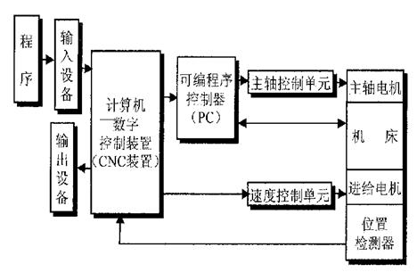
Figure 2 CNC system block diagram
In Fig. 1, 5 is a servo drive system, which includes a servo drive circuit (servo control line, power amplifier line) and a servo actuator such as a servo motor. They form a feed system of the numerical control device with the mechanical components on the working body, and the function is to convert the speed and displacement commands (pulse signals) sent from the numerical control device into the feed speed, direction and displacement of the executing components. The numerical control device can calculate and send a small enough pulse signal with sufficient speed and precision. The key is how high the servo system can respond to the execution. The accuracy and speed of the whole system depend mainly on the servo system. The servo drive circuit amplifies the weak electrical signal (about 5V, milliampere level) emitted by the numerical control device into a strong electric drive electric signal (tens, hundreds of volts, ampere level) to drive the actuator. The servo system actuators mainly include stepping motor, electro-hydraulic pulse motor, DC servo motor and AC servo motor. The function of the servo system is to convert the change of the electronic control signal into the angular velocity and angular displacement of the motor output shaft, thereby driving the mechanical body. The mechanical parts do the feed motion.
In Figure 1, 6 is the measuring device of the coordinate axis or actuator. The former is used to measure the actual position of the coordinate axis (such as the workbench), and the measurement result is fed back to the numerical control system (or servo drive system) to form a full closed loop control; the latter is used to measure the position of the servo motor shaft and provide feedback. , forming a semi-closed loop control. The introduction of the measurement feedback device effectively improves the dynamic characteristics of the system and greatly improves the machining accuracy of the parts.
In Fig. 1, 7 is an auxiliary control unit for controlling the work of other components, such as start and stop of the spindle, tool exchange, and the like.
In Figure 1, 8 is the coordinate axis, such as the X and Y axes of the plane motion table.
The working body of the numerical control system is the actual execution part of the machining movement, mainly including the main moving parts, the feed motion executing parts, the support parts such as the worktable and the bed column, and auxiliary devices such as cooling, lubrication, indexing and clamping. , the tool holder for storing the tool, the tool magazine or the automatic tool change mechanism for the exchange tool. The requirements for the working body are that there should be sufficient rigidity and vibration resistance, sufficient precision, small thermal deformation, simple structure of the transmission system, and easy automatic control.
Previous page
Spray Bottle,Plastic Spray Bottle,Spritzer Bottle,Spray Bottles For Cleaning
Foshan SUMEITE Grinding Technology Co.,Ltd , https://www.aedetail.com