"Line cutting method": the method of three-axis two-link machining, that is, the interpolation motion is performed by any two axes of the X, Y, and Z axes, and the other axis (axis) is periodically fed.
Machine origin: The zero point of the machine coordinate system. This origin is determined after the machine tool is commissioned and is the point inherent on the machine.
Machine coordinate system: The coordinate system with the machine origin as the origin of the coordinate system is the unique coordinate system of the machine tool, which is unique. The machine coordinate system is the reference coordinate system of the workpiece coordinate system established in the CNC machine. The machine coordinate system is generally not used as the programmed coordinate system, but only as the reference coordinate system of the workpiece coordinate system.
Workpiece origin: A point selected or associated with a part or fixture on the part that is convenient for programming. This point can also be coincident with the point.
Workpiece coordinate system: A coordinate system established by zero point of the workpiece origin. When programming, all dimensions are calculated based on this coordinate system. Modern CNC machine tools can be set up with multiple workpiece coordinate systems, which can be changed by G command during machining.
Workpiece origin offset: The distance between the workpiece origin and the machine origin after the workpiece is mounted on the machine with the fixture.
Relative coordinate programming: The end point coordinate value of the motion track is the programming mode relative to the starting point (incremental coordinate programming).
Parallel processing: refers to the method in which the CNC software system completes two or more tasks at the same time or at the same time interval. The purpose of using parallel processing technology is to improve the utilization of CNC system resources and the processing speed of the system. The implementation of parallel processing is closely related to the hardware structure of the CNC system.
Front-end structure: This structure mode divides the CNC system software into two parts: the foreground program and the background program. The former mainly performs real-time tasks such as interpolation calculation, position control, and fault diagnosis. It is a real-time interrupt service program. The background program (also called the background program) completes the weak real-time tasks such as display, editing and management of part processing programs, system input/output, interpolation preprocessing (decoding, tool compensation processing, speed preprocessing), etc. A program that runs in a loop, during the running process, is constantly interrupted by the foreground interrupt program, and the front and back are coordinated to complete the processing of the part.
Interrupt type structure: This structure is to arrange each task module of the whole system software in different levels of interrupt service program except the initialization program, and then interrupt management system (composed of hardware and software) The program implements scheduling management.
Interpolation: A method of determining some intermediate points between known points of a contour according to the given feed rate and the requirements of a given contour. This method is called the interpolation method or the interpolation principle. For each method (principle), there may be different calculation methods. This specific calculation method is called interpolation algorithm.
Tool radius compensation: During the machining process, the CNC machine controls the trajectory of the tool center. For the sake of convenience, the user always compiles the machining program according to the contour of the part. Therefore, in order to process the required part contour, during the inner contour machining The tool center must offset a tool radius value from the inside of the part; when performing outer contour machining, the tool center must offset a tool radius value to the outside of the part. According to the program programmed according to the contour of the part and the preset offset parameters, the function that the numerical control device can automatically generate the tool center trajectory in real time is called the tool radius compensation function.
Previous page next page
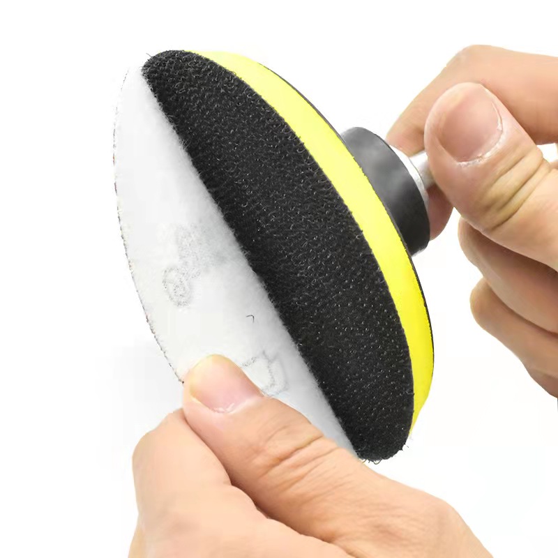
Excellent balance: the balance is important when polishing. The reinforced inner structure keeps the plate stable and smooth. High-quality material and advanced production technology ensure the pad balance.Resistance to heat, and reducing heat transfer to the paint surface.The better balanced a backing pad is, the less fatigue you feel when polishing or waxing car.The Velcro backing has extra gripping power and it is strong.works well and has not shown any sign of wear after about 50 hours of use.Backing pads are Widely used in grinding and polishing artificial stone, furniture and wood products, metals, cars and other items.
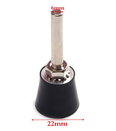
High Flexible durability, This Roloc disc back holder is made of reinforced rubber material, longer life time than other products.Widely used with various types of discs, Mini flap discs, quick change discs, Surface Conditioning Discs, strip discs and Roloc bristle discs etc.The 1/4 shank fits drills, air powered die grinders, and other Power Tools and air tools.Max speed of 30000RPM, full range size of 1in 1.5inch 2in 3inch are available.
We distributes and wholesales various brands of Bonded Abrasives , Abrasive Sanding Disc, Cutting Wheels , Flap Wheels , Flap Disc Backing Pad , Flap Disc Adhesive , and Surface Conditioning Product etc, and enjoy a high position among consumers.
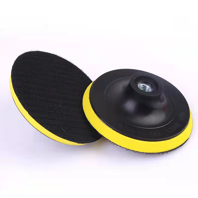
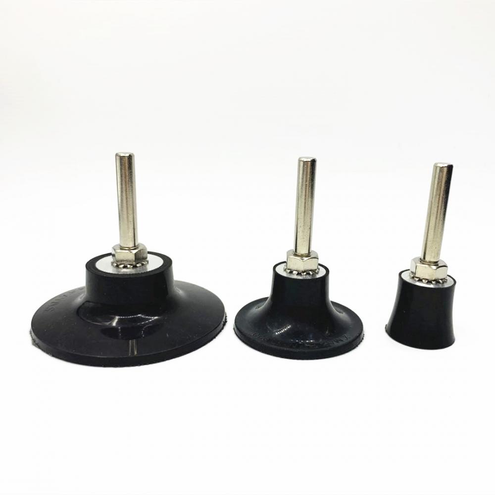
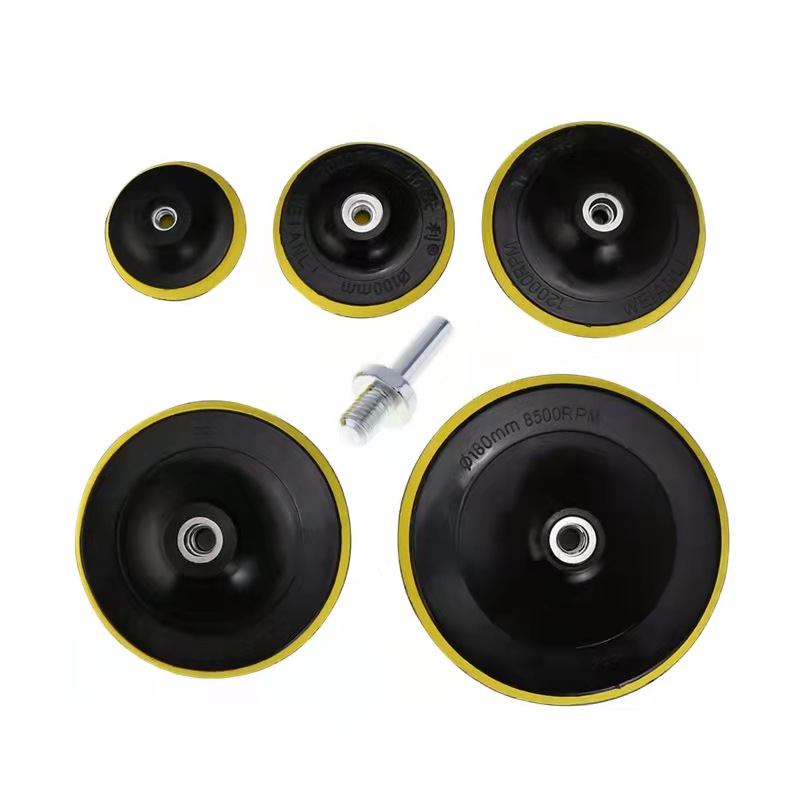
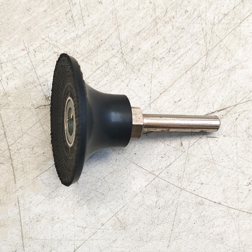
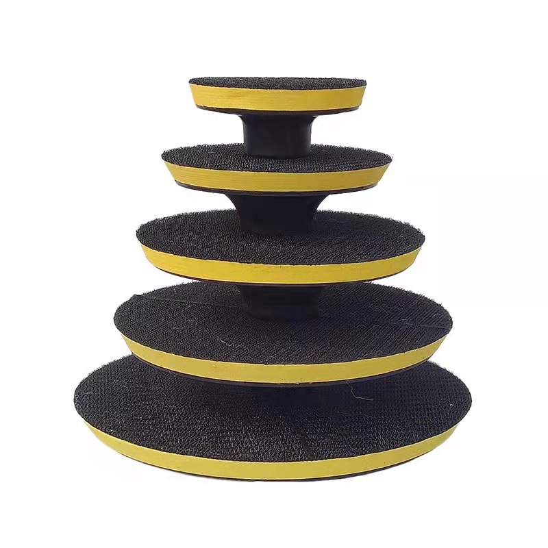
Sanding Disc Backing Pad,Hook And Loop Pad,Disc Pad Holder,Sander Replacement Pad,grinder backing plate
Zhengzhou Jiading Abrasive Manufacturing Co.,Ltd , https://www.abrasive-jd.com