Abstract: This paper mainly introduces a remote intelligent voice anti-theft alarm system with single-chip AT89C52, ISDl420 voice circuit, analog off-hook circuit and dialing circuit as the core, and elaborates on its basic working principle and circuit composition. The system can realize automatic dialing, call the alarm signal through the ordinary telephone line, and notify the victim in time. The system has a high degree of program, applicability, and flexible functions, and can be widely used in important occasions such as homes, stores, and banks.
In modern society, people's awareness of safety is getting higher and higher. Some important places, such as families, banks, shops, etc., install anti-theft devices to protect life and property. Early security equipment was generally mechanical (such as security doors, security windows), low protection factor, poor security, and the application space is getting smaller and smaller. With the development of science and technology, people have developed a series of automatic alarm systems such as magnetic door, touch type, radar monitoring, infrared monitoring, etc. These alarm systems have high degree of automation, strong applicability and certain intelligence. However, most systems are unable to notify the victim in time when an alert is issued. In view of this situation, this paper designs a remote intelligent voice anti-theft alarm system based on AT89C52. The system finds that the thief can dial the number in time, and can use the ordinary telephone line to make an alarm signal call, and notify the victim in time. The system has the characteristics of high intelligent program, strong practicability, reliable performance and stability.
1 basic working principle
The system consists of AT89C52 single-chip microcomputer, signal detection circuit, reset circuit, telephone number preset circuit, ringing detection circuit, analog off-hook circuit, dialing circuit and voice circuit. The system block diagram is shown in Figure 1.
The DTMF code transmission circuit sends out a telephone number stored in the CPU by the user through a telephone number input circuit, and the number can be set arbitrarily, and can be a local program-controlled telephone, a mobile phone, or the like.

Figure 1 Schematic diagram of remote intelligent voice anti-theft alarm system
The flow chart is shown in Figure 2. When the signal detection circuit detects that someone has broken in, it will issue a trigger signal. This signal is sent as an alarm signal and sent to the CPU after amplification. After a certain delay, if the master enters, it can be The reset circuit is used to initialize it for a certain period of time. Otherwise, the alarm is prepared. The CPU first checks the output of the ringing current signal detection circuit. If the output is a high level, the user's telephone rings, and the dialing cannot be off-hook. Time processing, only when the output is low, the CPU instructs the analog off-hook circuit to go off-hook, sends the DTMF phone number, and calls the preset caller. At this time, there will be two situations: the called party is busy and the called party rings. If the previous situation occurs, perform analog hang up, delay and then pick up the phone; if the party rings and picks up the phone, it will start to send the signal tone or voice signal recorded in ISDl420, and finally hang up.
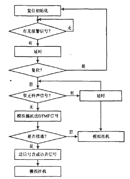
Figure 2 system work flow chart
2 main components
The components used in this system include AT89C52 single-chip microcomputer, 8255A programmable parallel interface chip, digital audio recording and playback chip ISDl420, dual-tone multi-frequency transceiver Receiver MT8888, DTMF encoder CSC5087, DTMF decoder SC8870, P2288 passive heat Discharge the human body infrared sensor and so on.
2.1 AT89C52 single-chip microcomputer
AT89C52 series MCU has a larger capacity memory, and its chip has 40 pins, including 2 dedicated main power pins, 2 external crystal pins, 4 control signals and other power supply multiplexed pins. And 32 input and output I / O pins. In this system, the input and output I/O pins of the AT89C52 are processed, and the application of four control signals or pins with other power supplies is used.
/tT89C52 has four 8-bit parallel input/output I/O interfaces: P0 port, P1 port, P2 port, P3 port (32 lines in total) for parallel input or output data.
(1) P0 port (32 feet to 39 feet): P0.O~P0.7 are collectively referred to as P0 port. When the external memory is not connected and the I/O interface is not extended, the P0 port is an address/data time division multiplexing port, which provides an 8-bit address bus and an 8-bit bidirectional data bus in a time sharing manner.
(2) P1 port (1 pin to 8 pin): P1.0~P1.7 are collectively referred to as P1 port and can be used as a quasi-bidirectional I/O interface. When programming E2PRoM and performing program verification, the P1 port receives the input low 8-bit address.
(3) P2 port (21 feet ~ 28 feet): P2.0 ~ P2.7 are collectively referred to as P2 port, generally used as quasi-bidirectional I / 0 interface. When an external memory or extended I/O interface is connected and the addressing range exceeds 256 B, the P2 port is used to send a high 8-bit address to the upper 8-bit address bus.
(4) P3 port (10 feet ~ 17 feet): P3.o ~ P3.7 are collectively referred to as P3 port. It is a dual-function port that can be used as a general quasi-bidirectional I/O interface. It can also be used for every second bit, and each pin of the P3 port can be independently defined as the input or output of the first function or the first function. 2 features.
In the hardware circuit design, because the system has extended the I/O interface, that is, the programmable parallel I/O interface 8255A is extended outside the chip of the AT89C52, so the P0 port of the AT89C52 of the single chip is used as the interface with the address latch 74HC373. The P0 port is used as an address bus or data bus, while the P3 port utilizes its second function.
2.2 programmable parallel I / O interface chip 8255A
The 8255A has three 8-bit data ports, Port A, Port B, and Port C. The three ports have different functions in different modes of operation.
The 8255A has three modes of operation: Mode 0, Mode 1 and Mode 2. These modes of operation can be specified by software programming. In this system, the 8255A works in the 0 mode. Mode 0 is the "basic input and output mode". This mode of operation does not require any strobe signal. The upper 4 bits and lower 4 bits of port A, port B and port C can be set as inputs or outputs.
When used as an output port, the output data is latched. When used as an input port, the data of port A can be latched, and the data of port B and port C cannot be latched. In mode 0, the peripheral can provide data to the microprocessor at any time, and the peripheral can accept the data sent by the microprocessor at any time. No "strobe" and "state" signals are required before data transfer, as long as the RD or WR signal is active, data transfer is possible. In addition, the upper 4 bits and the lower 4 bits of the C port can be separately programmed in the working mode control word. However, it should be noted that the transmission of the C-port data is performed in units of bytes, and it is not possible to read and write the upper 4 bits or the lower 4 bits separately.
2.3 digital audio recording and playback chip ISDl420
   Digital audio recording and playback chip ISDl420 is a new single-chip high-quality voice recording and playback circuit produced by American ISD Company. It has a patented analog 'processing storage method, which makes the recording and playback sound quality excellent, no common background noise, and the voice content is still after the circuit is powered off. Not lost. ISD series voice recording and playback components include 64 kB/128 kB E2PRoM memory, noise-eliminating mic preamp and automatic gain adjustment AGC circuit, dedicated filter circuit for voice, clock oscillation circuit with extremely high temperature stability and full voice processing Circuit. It has the characteristics of full patch miniaturization, easy to use, voice recording, power off voice storage, micro power consumption, direct push speaker, sound quality and tape effect. This circuit also offers a variety of application options and interfaces, and can be easily applied to a variety of integrated electronic voice systems.
3 circuit design
3.1 signal detection circuit
The sensor in Figure 3 is the P2288 passive pyroelectric human body infrared sensor. It works in a balanced differential mode and only senses the infrared radiation of active human body at 7~14um wavelength, which is not affected by ambient temperature and visible light. After the infrared radiation of the active human body is detected by the sensor, the sensor will generate a weak electrical signal, which is filtered, amplified, and sent to the bidirectional comparator. In order to prevent malfunction, the signal will be compared with the threshold level to generate a pulse signal output, and the high level is sent as an alarm signal to the CPU.

Figure 3 signal detection working circuit block diagram
3.2 reset circuit
This system uses the RC reset mode, and the RC reset circuit is shown in Figure 4. When the system is powered up, the circuit provides a valid reset signal, RST (high), until the system power is stabilized and the reset signal (low level) is removed. In actual design, usually C1 takes a value of 10uF or more, and R1 usually takes a value of about 10k. If the value is too small, the RST signal drive capability will be poor and the system will not be reliably reset. In addition, the freewheeling diode VD1 connected by the broken line in the figure plays an important role in improving the reset performance. Its function is to discharge the capacitor quickly when the power supply voltage drops instantaneously. The buttons in the figure are for the convenience of the owner to reset the circuit.

Figure 4 reset circuit diagram
3.3 Phone number preset circuit
This part of the circuit is designed to facilitate the user to enter the phone number.
When there is an alarm, the system will dial the pre-recorded phone number for remote alarm. Here, a 4 row and 4 column keyboard should be designed. For the convenience of software design, 16 keys can be connected through two 74HC245, through simple query. The program can enter the keyboard input value.
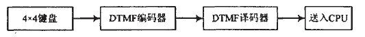
Figure 5 Phone number preset circuit working block diagram
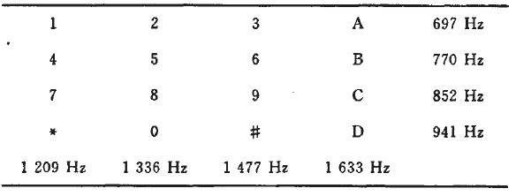
The DTMF encoder in the figure uses the CSC5087, which generates a set of dual audio signals based on different buttons. CCITT (International Telegraph and Telephone Consultative Committee) specifies the combination of buttons and high and low frequency groups. For example, press the "8" key to issue the DTMF signal at fL=852 Hz, fH=1 336 Hz. The DTMF decoder is the SC8870 decoder, which translates each DTMF signal into a 4-bit binary code output, 16 The DTMF signals correspond to a total of 16 binary codes of 0000~1111.
For example, for the DTMF signal sent by the CSC5087 with fL=852 Hz and fH=1336Hz, the SC8870 decodes and outputs the "1000" code, corresponding to the button "8".
Ringing detection circuit: When a call is made, the system determines the number of rings, which is a predetermined number of times and the phone still picks up the system and will automatically pick up the phone. The telephone ringing signal is input to the TO pin of the AT89C52 through the photocoupler TP521, and is counted. When the ringing signal is received, if the user does not pick up the phone after continuous ringing for 10 times, the voice alarm system is automatically switched to the remote voice alarm system. The CPU sets "1" corresponding pin output signal to realize automatic off-hook function. If the owner connects the phone during 10 rings, the controller does not respond, so that the controller and the phone do not interfere with each other. After off-hook, the dual-tone multi-frequency signal output by the MT8888 is detected, and the remote information sent by the user is read out to realize the remote communication and control functions.
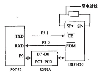
Figure 6 ringing detection and analog off-hook hang-up circuit
Automatic off-hook hang-up: Automatic off-hook is a prerequisite for remote alarm and receiving calls. The program-controlled telephone exchange judges whether the telephone line is off-hook based on the fact that the loop current suddenly increases to about 30 A, and the telephone is considered to be off-hook. This circuit is designed accordingly. When there is an alarm signal or there is a call from outside, when the system needs to pick up the phone and turn on the phone, the P1.7 port of the single chip becomes high level, so that the NPN transistor 5551 is turned on, and then the 5041 is turned on, so that the telephone loop is turned on. Automatic off-hook. When the P1.7 port goes low, the system hangs up.
3.5 dialing circuit
   The dialing circuit is a function of judging the transmission and reception of DTMF and signal sound by using MT8888. When the DTMF signal is to be transmitted, the MT8888 is set to the DTMF transmission mode, and the MCU sends each bit of the telephone number to the MT8888, and converts the corresponding DTMF signal to the telephone line for automatic dialing. The two-tone multi-frequency signals corresponding to the respective numbers are as shown in Table 1.
Table 1 number one signal frequency comparison table
In the case of selecting the burst mode, the MT8888 can generate an interrupt signal to the microcontroller every time a phone number is sent. DO~D3 in Figure 7 is connected to P1.0~P1.3.MT8888 of AT89C52.  The end is connected to the TO of the AT89C52.
  The square output wave that corresponds to the sine wave input from the TONE end, and the number of square waves can be used to judge various signal tones. When judging the signal tone, MT8888 is set to the tone sound judgment mode (CALL mode), and then the TO counter pair is activated.
  The output signal of the terminal is counted, because the ringback tone is a signal of 1 s to 4 S off, so the count time is 5 S, and because the dial tone is a 450 Hz continuous signal, the busy tone is 0.35 S pass 0.35 S off, if counting The value is 350~550 (450*1=450), it is ringback tone, 2 150~2 350 (450*5=2 250) is dial tone, the count value is 1 025~1 225 (450*5/2-1) 125) For the busy tone, the tone is a continuous sine wave of 950 Hz, so the value is greater than 4 000. The range of the value can be adjusted appropriately. This article uses up and down 100 errors.
Figure 7 schematic diagram of the dialing circuit
3.6 voice circuit
The voice circuit records and plays the voice signals that the user wants to alarm in the alarm system. These voice signals can be pre-recorded by the user and can be modified at any time. The voice circuit is mainly composed of a single chip microcomputer 89C52 and a digital audio recording and playback chip ISDl420, and the schematic diagram is shown in FIG.
The working principle is that when the remote voice intelligent anti-theft alarm system detects that someone has illegally entered, the alarm system issues an alarm signal, and the single-chip microcomputer serially communicates with the voice synthesis chip ISDl420 through the serial communication data bus P3.0, P3.1, and controls. ISDl420 voice synthesis (combining related words that have been manually entered from outside) and output, amplified by a triode and rectified by a bridge bridge, sent to the telephone line, exchanged by the switch and sent to the designated phone or mobile phone .
Figure 8 schematic diagram of the voice circuit
4 Conclusion
The remote intelligent voice anti-theft alarm system based on AT89C52 designed in this paper uses the program-controlled telephone network as the transmission medium to notify the parties in time of emergency, even if it is not near the scene, it can automatically call the alarm. Compared with the ordinary alarm system, the system will focus on the remote intelligent voice burglar alarm. In addition, through the expansion of its input port, it can form a multi-function alarm system such as fire alarm and gas leakage alarm, which has important practical significance and promotion value.
references:
[1]. AT89C52 datasheet http://
[2]. 8255A datasheet http://
[3]. MT8888 datasheet http://
[4]. P2288 datasheet http://
[5]. 74HC373 datasheet http://
[6]. 74HC245 datasheet http://
[7]. TP521 datasheet http://
Medium Duty Casters,Gray Rubber Caster,Rubber Caster
Gas Burner & Gas Stove Co., Ltd. , http://www.nshardwares.com